Semiconductor device and method for manufacturing the same

a semiconductor and glass substrate technology, applied in semiconductor devices, digital storage, instruments, etc., can solve the problems of not being able to be manufactured over a larger glass substrate, and achieve the effect of reducing the channel length of the transistor, reducing the band gap, and reducing the effective channel length

Active Publication Date: 2012-06-28
SEMICON ENERGY LAB CO LTD
View PDF5 Cites 58 Cited by
  • Summary
  • Abstract
  • Description
  • Claims
  • Application Information

AI Technical Summary

Benefits of technology

[0029]In the second oxide semiconductor region to which the ions are added, the band gap becomes small in some cases. In that case, the use of the second oxide semiconductor regions as the source region and the drain region has such an effect that a band edge of a channel which is formed with the first oxide semiconductor region to which the ions are not added is hardly curved. On the other hand, in the case where the source region and the drain region are formed using a metal material, the degree of a curve of the band edge of the channel which is the first oxide semiconductor region is not negligible, so that the effective channel length is decreased in some cases. This tendency becomes more remarkable as the channel length of a transistor is reduced. Therefore, when the second oxide semiconductor regions to which the ions are added is used as the source region and the drain region, a short-channel effect can be suppressed.
[0030]In addition, by forming the second oxide semiconductor regions to which the ions are added as the source region and the drain region of the transistor, contact resistance between a wiring and the source region and between a wiring and the drain region can be reduced, which increases the on-state current of the transistor.
[0031]In accordance with an embodiment of the present invention, it is possible to provide a semiconductor device including a transistor in which variation in electric characteristics due to a short-channel effect is less likely to be caused. It is also possible to provide a semiconductor device which is miniaturized. In addition, it is possible to provide a semiconductor device whose on-state current is improved.

Problems solved by technology

On the other hand, although transistors manufactured using polycrystalline silicon have high field-effect mobility, they are not suitable for being manufactured over a larger glass substrate.

Method used


Image

  • Semiconductor device and method for manufacturing the same
  • Semiconductor device and method for manufacturing the same
  • Semiconductor device and method for manufacturing the same

Examples


embodiment 1

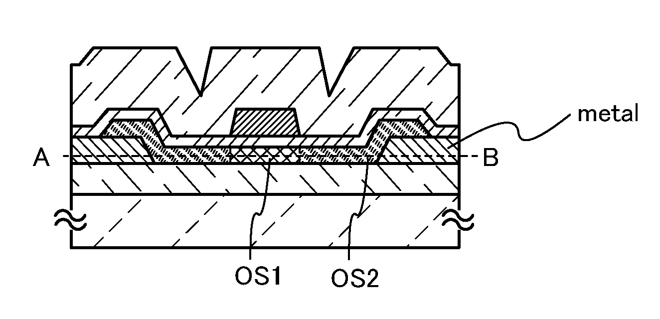
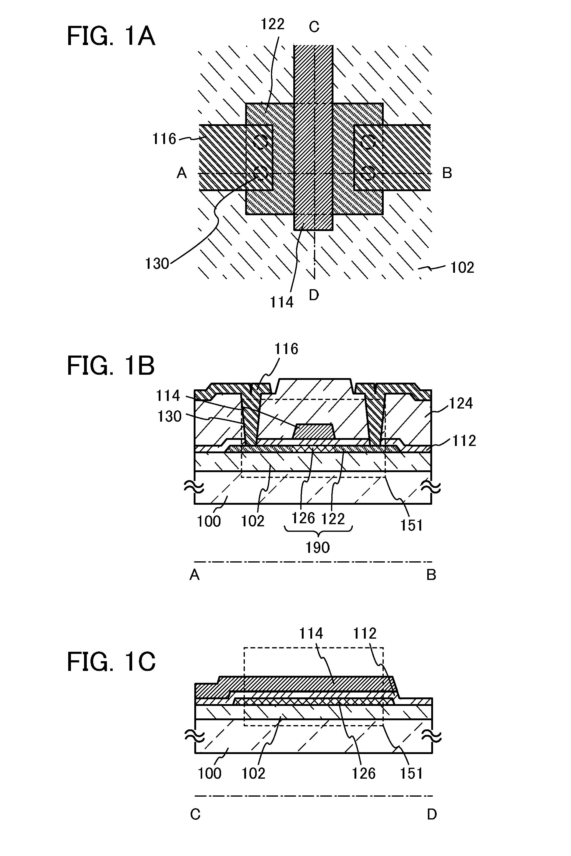
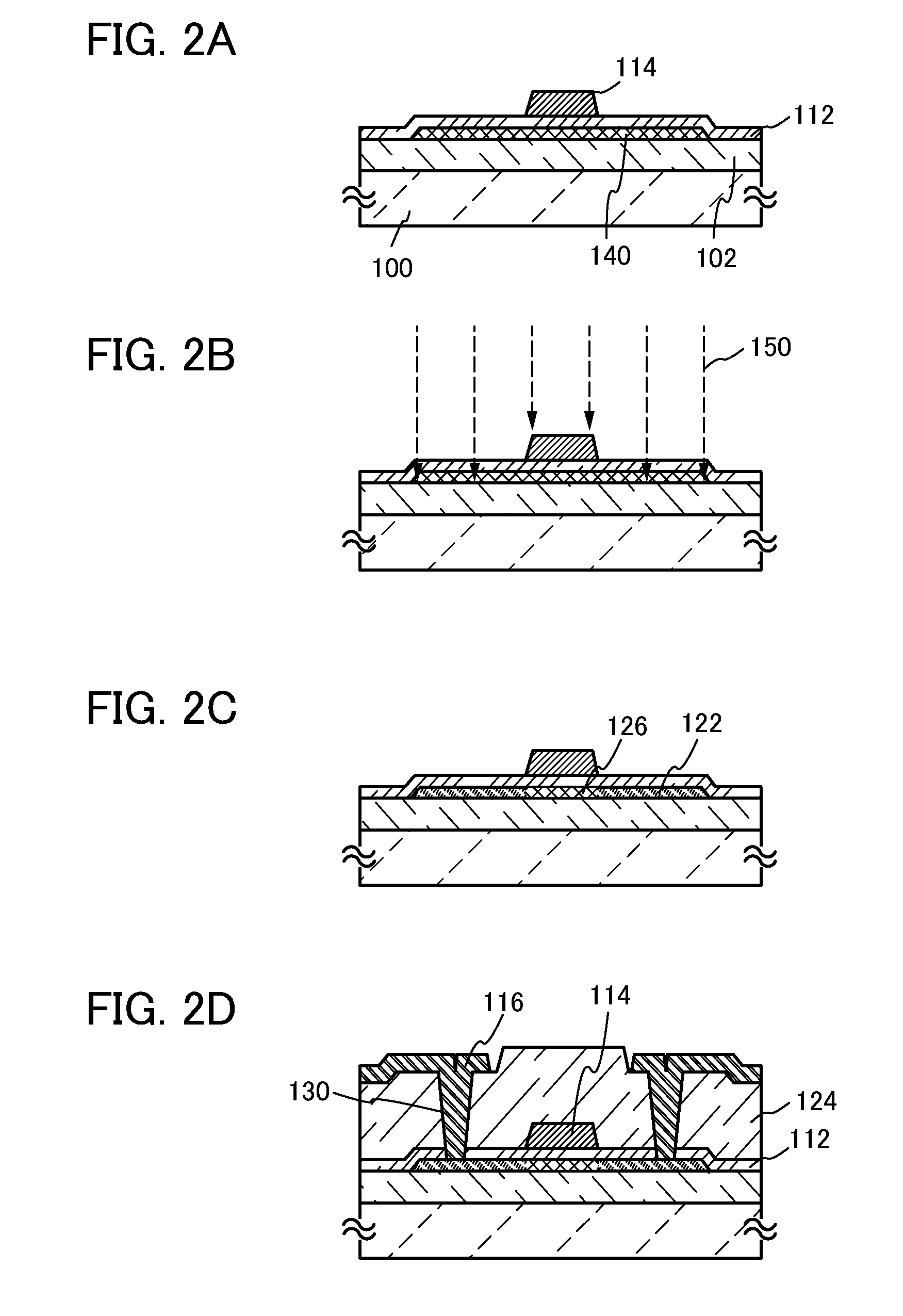
[0049]In this embodiment, an example of a top-gate transistor in which a channel region is formed using a first oxide semiconductor region to which ions are not added, and a source region and a drain region are formed using second oxide semiconductor regions to which ions are added and which are in the same layer as the channel region will be described with reference to FIGS. 1A to 1C and FIGS. 2A to 2D.

[0050]FIGS. 1A to 1C are a top view and cross-sectional views of a top-gate transistor. Here, FIG 1A is a top view, FIG. 1B is a cross-sectional view taken along A-B in FIG. 1A, and FIG. 1C is a cross-sectional view taken along C-D in FIG. 1A. Note that in FIG. 1A, some components of a transistor 151 (e.g., a gate insulating film 112 and an interlayer insulating film 124) are omitted for simplicity.

[0051]The transistor 151 illustrated in FIGS. 1A to 1C includes an oxide semiconductor film 190 over an insulating surface which includes a first oxide semiconductor region 126 and a pair ...

embodiment 2

[0120]In this embodiment, an example of a transistor which is different from the transistor described in Embodiment 1 will be described with reference to FIG. 3 and FIGS. 4A to 4D.

[0121]A transistor 152 illustrated in FIG. 3 includes a base insulating film 102 over a substrate 100, source and drain electrodes 216 over the base insulating film 102, an oxide semiconductor film 290 over the base insulating film 102 which includes a first oxide semiconductor region 226 and a pair of second oxide semiconductor regions 222 connected to the source and drain electrodes 216, a gate insulating film 212 over the oxide semiconductor film 290, a gate electrode 214 over the gate insulating film 212, and an interlayer insulating film 224 over the gate insulating film 212 and the gate electrode 214.

[0122]The channel length of the transistor is determined by the distance between the pair of second oxide semiconductor regions 222. The channel length is preferably equal to the width of the gate electr...

embodiment 3

[0133]In this embodiment, an example of a transistor which is different from the transistors described in Embodiments 1 and 2 will be described with reference to FIG. 5 and FIGS. 6A to 6D.

[0134]A transistor 153 illustrated in FIG. 5 includes a substrate 100 having an insulating surface, a gate electrode 314 over the substrate 100, a gate insulating film 312 over the gate electrode 314, an oxide semiconductor film 390 which is provided over the gate electrode 314 with the gate insulating film 312 interposed therebetween and includes a first oxide semiconductor region 326 and a pair of second oxide semiconductor regions 322, an insulating film 319 which is provided over and to overlap with the first oxide semiconductor region 326, source and drain electrodes 316 connected to the pair of second oxide semiconductor regions 322, and an interlayer insulating film 324 over the insulating film 319 and the source and drain electrodes 316. Note that a base insulating film 102 may be provided ...


PUM


Abstract

A miniaturized semiconductor device including a transistor in which a channel formation region is formed using an oxide semiconductor film and variation in electric characteristics due to a short-channel effect is suppressed is provided. In addition, a semiconductor device whose on-state current is improved is provided. A semiconductor device is provided with an oxide semiconductor film including a pair of second oxide semiconductor regions which are amorphous regions and a first oxide semiconductor region located between the pair of second oxide semiconductor regions, a gate insulating film, and a gate electrode provided over the first oxide semiconductor region with the gate insulating film interposed therebetween. One or more kinds of elements selected from Group 15 elements such as nitrogen, phosphorus, and arsenic are added to the second oxide semiconductor regions.

Description

TECHNICAL FIELD[0001]The present invention relates to a semiconductor device which is provided with a circuit including a semiconductor element such as a transistor, and a method for manufacturing the semiconductor device. For example, the present invention relates to a power device which is mounted on a power supply circuit; a semiconductor integrated circuit including a memory, a thyristor, a converter, an image sensor, or the like; and an electronic device on which an electro-optical device typified by a liquid crystal display panel, a light-emitting display device including a light-emitting element, or the like is mounted as a component.[0002]In this specification, a semiconductor device means all types of devices which can function by utilizing semiconductor characteristics, and an electro-optical device, a light-emitting display device, a semiconductor circuit, and an electronic device are all semiconductor devices.BACKGROUND ART[0003]Transistors formed over a glass substrate ...

Claims


Application Information

Patent Timeline
Patent Type & Authority Applications(United States)
IPC IPC(8): H01L29/78H01L21/34
CPCH01L21/02554H01L29/7869H01L21/02631H01L21/02565G11C7/10H01L29/78693
Inventor YAMAZAKI, SHUNPEI
Owner SEMICON ENERGY LAB CO LTD
Why Eureka
Try Eureka