Power state synchronization in a multi-core processor

a multi-core processor and power state technology, applied in the direction of instruments, computation using denominational number representation, generating/distributing signals, etc., can solve the problems of multi-core processor waste, complex power management actions, and chipset cannot be given permission to disable the bus clock

Active Publication Date: 2012-06-28
VIA TECH INC
View PDF6 Cites 66 Cited by
  • Summary
  • Abstract
  • Description
  • Claims
  • Application Information

AI Technical Summary

Benefits of technology

[0013]In another aspect of the present invention, a multi-core processor is provided comprising a plurality of enabled physical processing cores and a configurable resource shared by two or more of the cores, wherein configurations of the resource affect the power, speed, or efficiency with which the cores sharing the resource are able to operate. The processor further includes, for each core, internal core power state management logic configuring each core to participate in a de-centralized inter-core power state discovery process carried out between the cores without the assistance of centralized non-core logic. The internal core power management logic configures the core to instigate implementation of a composite target power state configuring the shared resource, if the core is designated as a master core for the purpose of configuring the shared resource and the composite target power state is discovered through the de-centralized inter-core power state discovery process. The composite target power state is a most power-conserving power state for the shared resource that will not interfere with any corresponding target power state of each core sharing the resource.
[0014]In a related aspect, a decentralized method of managing power states for a multi-core processor is provided. A core receives a target power state affecting a configurable resource shared between itself and at least one other core, wherein the target power state defines a configuration of the resource that would affect the power, speed, or ef

Problems solved by technology

Finally, in some instances the microprocessor may even remove power altogether to portions of its circuitry.
Performing the power management actions is complicated by the fact that many modern microprocessors are multi-core processors in which multiple processing cores share one or more power management-related resources.
That is, the chipset cannot be given permission to disable the bus clock until all the cores are prepared for the chipset to do so.
In this state, it is wasteful for the multi-core processor to wake up in response to the snoop c

Method used


Image

  • Power state synchronization in a multi-core processor
  • Power state synchronization in a multi-core processor
  • Power state synchronization in a multi-core processor

Examples


Embodiment Construction

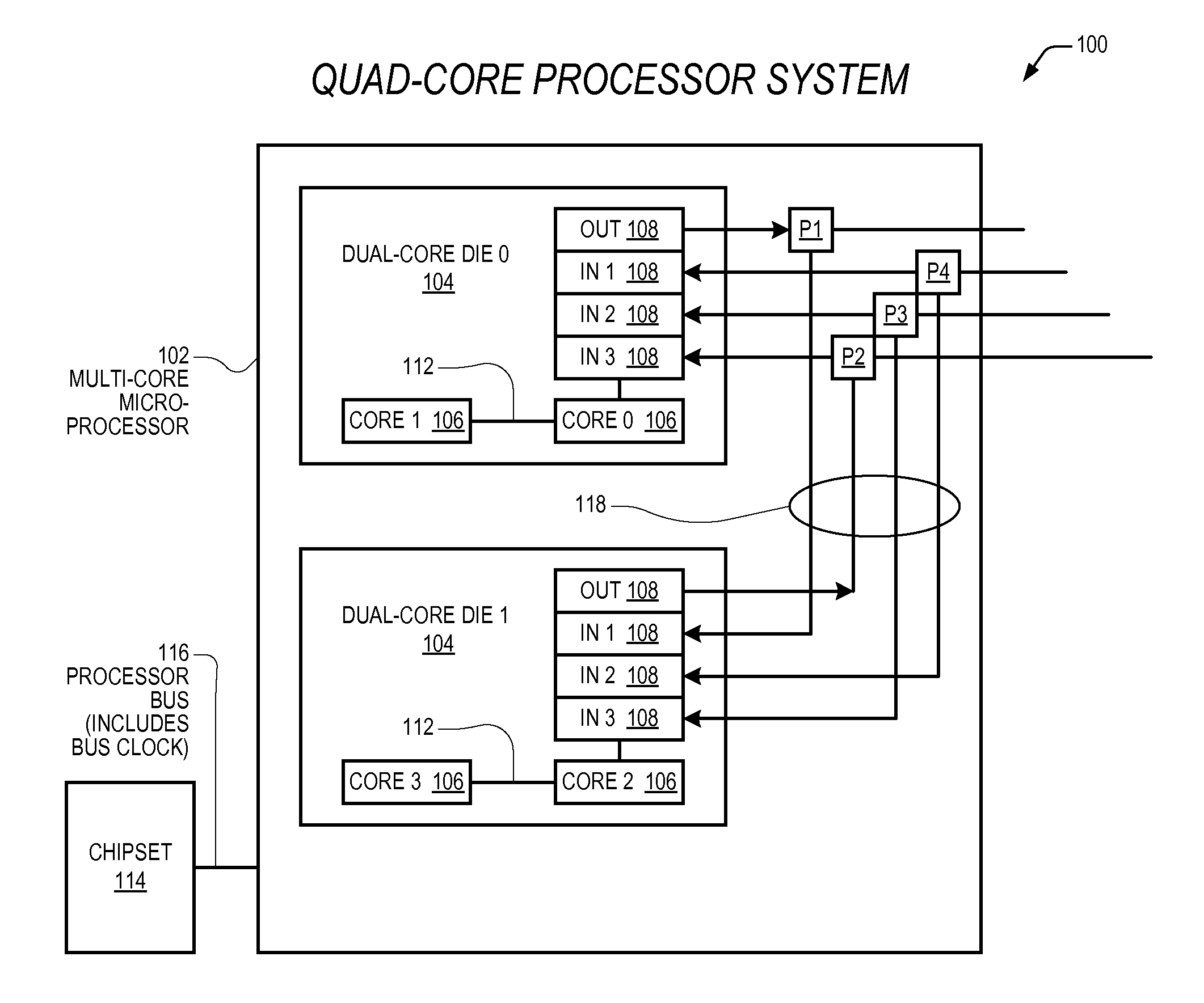
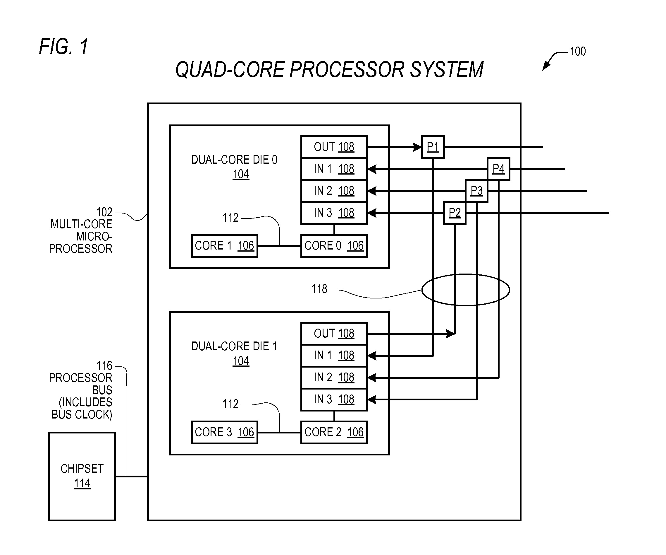
[0045]Described herein are embodiments of systems and methods for coordinating, synchronizing, managing, and implementing power, sleep or operating states on a multi-core processor, using decentralized, distributed logic that is resident and duplicated on each core. Before describing each of the Figures, which represent detailed embodiments, more general applicable concepts of the invention are introduced below.

I. Multi-Layer Multi-Core Processor Concepts

[0046]As used herein, a multi-core processor generally refers to a processor comprising a plurality of enabled physical cores that are each configured to fetch, decode, and execute instructions conforming to an instruction set architecture. Generally, the multi-core processor is coupled by a system bus, ultimately shared by all of the cores, to a chipset providing access to peripheral buses to various devices. In some embodiments, the system bus is a front-side bus that is an external interface from the processor to the rest of the ...


PUM


Abstract

A multi-core processor includes microcode distributed in each core enabling each core to participate in a de-centralized inter-core state discovery process. In a related microcode-implemented method, states of a multi-core processor are discovered by at least two cores participating in a de-centralized inter-core state discovery process. The inter-core state discovery process is carried out through a combination of microcode executing on each participating core and signals exchanged between the cores through sideband non-system-bus communication wires. The discovery process is unmediated by any centralized non-core logic. Applicable discoverable states include target and composite power states, whether and how many cores are enabled, the availability and distribution of various resources, and hierarchical structures and coordination systems for the cores. The inter-core state discovery process may be carried out in accordance with various hierarchical coordination systems involving chained inter-core communications.

Description

CROSS REFERENCE TO RELATED APPLICATION(S)[0001]This application claims priority based on U.S. Provisional Application Ser. No. 61 / 426,470, filed Dec. 22, 2010, entitled MULTI-CORE INTERNAL BYPASS BUS, which is hereby incorporated by reference in its entirety.[0002]This application is related to the following co-pending U.S. patent applications which are concurrently filed herewith, each of which is hereby incorporated by reference in its entirety.SerialFilingNumberDateTitleTBDhere-MULTI-CORE INTERNAL BYPASS BUS(CNTR.2503)withTBDhere-DECENTRALIZED POWER MANAGEMENT(CNTR.2527)withDISTRIBUTED AMONG MULTIPLEPROCESSOR CORESTBDhere-RETICLE SET MODIFICATION TO PRODUCE(CNTR.2528)withMULTI-CORE DIESTBDhere-DYNAMIC MULTI-CORE MICRO-(CNTR.2533)withPROCESSOR CONFIGURATION DISCOVERYTBDhere-DISTRIBUTED MANAGEMENT OF A(CNTR.2534)withSHARED POWER SOURCE TO A MULTI-CORE MICROPROCESSORTBDhere-DYNAMIC AND SELECTIVE CORE(CNTR.2536)withDISABLEMENT AND RECONFIGURATIONIN A MULTI-CORE PROCESSORFIELD OF THE ...

Claims


Application Information

Patent Timeline
IPC IPC(8): G06F1/32G06F1/12G06F9/22
CPCG06F1/3206G06F1/3237G06F1/324G06F1/3287G06F1/3296Y02B60/142G06F1/26Y02B60/1217Y02B60/1282Y02B60/1285Y02B60/1221G06F9/5094Y02D10/00
Inventor HENRY, G. GLENNGASKINS, DARIUS D.
Owner VIA TECH INC
Why Eureka
Try Eureka