Unwindable Flat Solar Generator

a solar generator and winding technology, applied in the direction of pv power plants, transportation and packaging, cosmonautic vehicles, etc., can solve the problems of violent and uncontrollable unfolding, conventional tape-springs may present difficulties in controlling unfolding, and whole tape-springs may have a tendency to straighten out simultaneously, etc., to achieve the effect of rigid bearing structur

Inactive Publication Date: 2012-07-05
THALES SA
View PDF6 Cites 23 Cited by
  • Summary
  • Abstract
  • Description
  • Claims
  • Application Information

AI Technical Summary

Benefits of technology

[0014]More precisely, the subject of the invention is a solar generator deployment device comprising an assembly comprising a plurality of tape-springs supporting a windable membrane on a face of which is arranged a plurality of elements capable of converting the solar energy into electrical energy, characterized in that, in the wound state, said tape-springs and said membrane are co-wound around a unique radius of curvature equal to the natural radius of curvature of folding of the tape-spring and in that said tape-springs are substantially parallel and interlinked by transversal braces ensuring the rigidity of the bearing structure.

Problems solved by technology

If this force is abruptly eliminated, the unfolding can be violent and uncontrolled, which means that the whole tape-spring may have a tendency to straighten out simultaneously, over its entire length.
Conventional tape-springs may thus present difficulties when it comes to controlling their unfolding.
However, this type of device can be used only once, because the polymerization is irreversible.
This poses a problem for demonstrating and validating the complete deployment on the ground before being sent into space.

Method used


Image

  • Unwindable Flat Solar Generator
  • Unwindable Flat Solar Generator
  • Unwindable Flat Solar Generator

Examples


Embodiment Construction

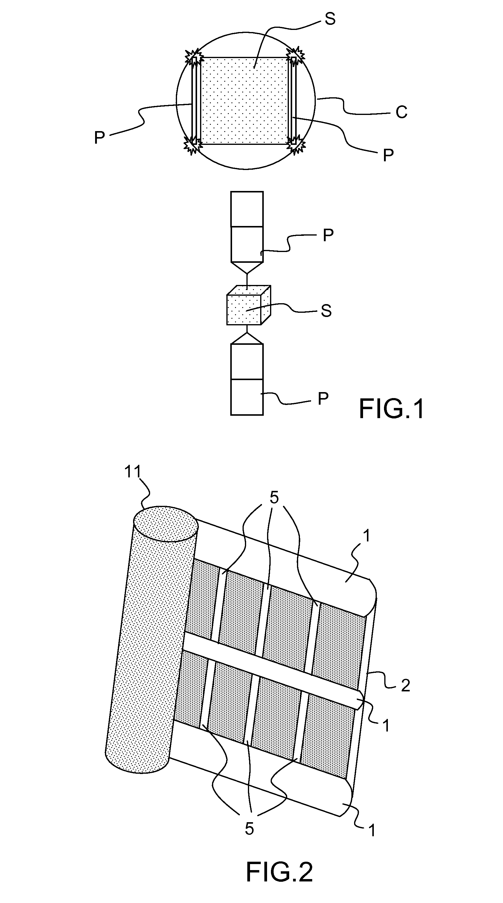
[0033]FIG. 1 shows a device example of known rigid solar panels P, intended to be deployed on either side of a body of a spacecraft S, in the configuration stored in the nose cone C of a launch vehicle and in deployed configuration. As stated previously, the rigid solar panels P form, in the nose cone C, a bulk that is significant and not optimized relative to the volume allotted in the nose cone C.

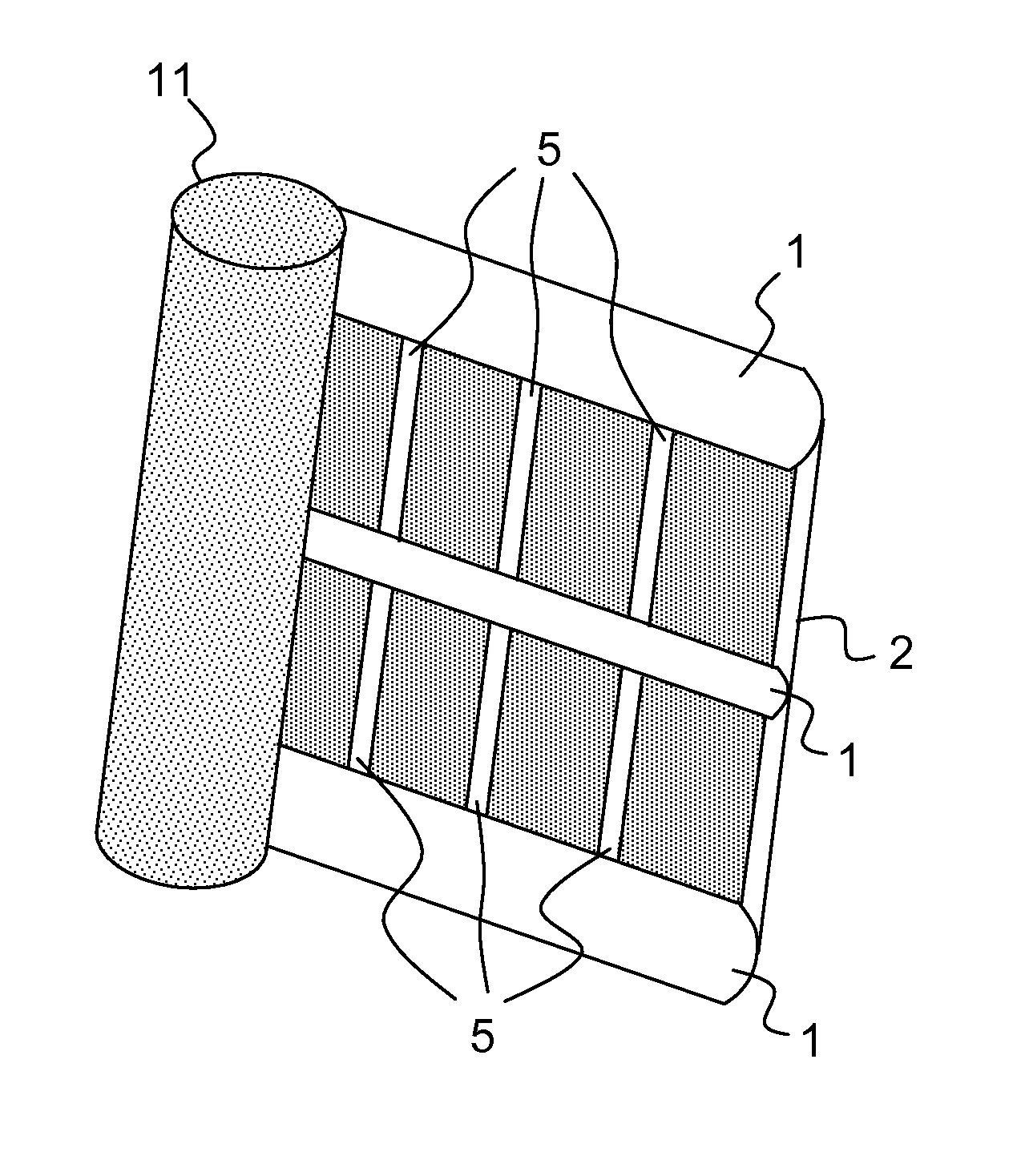
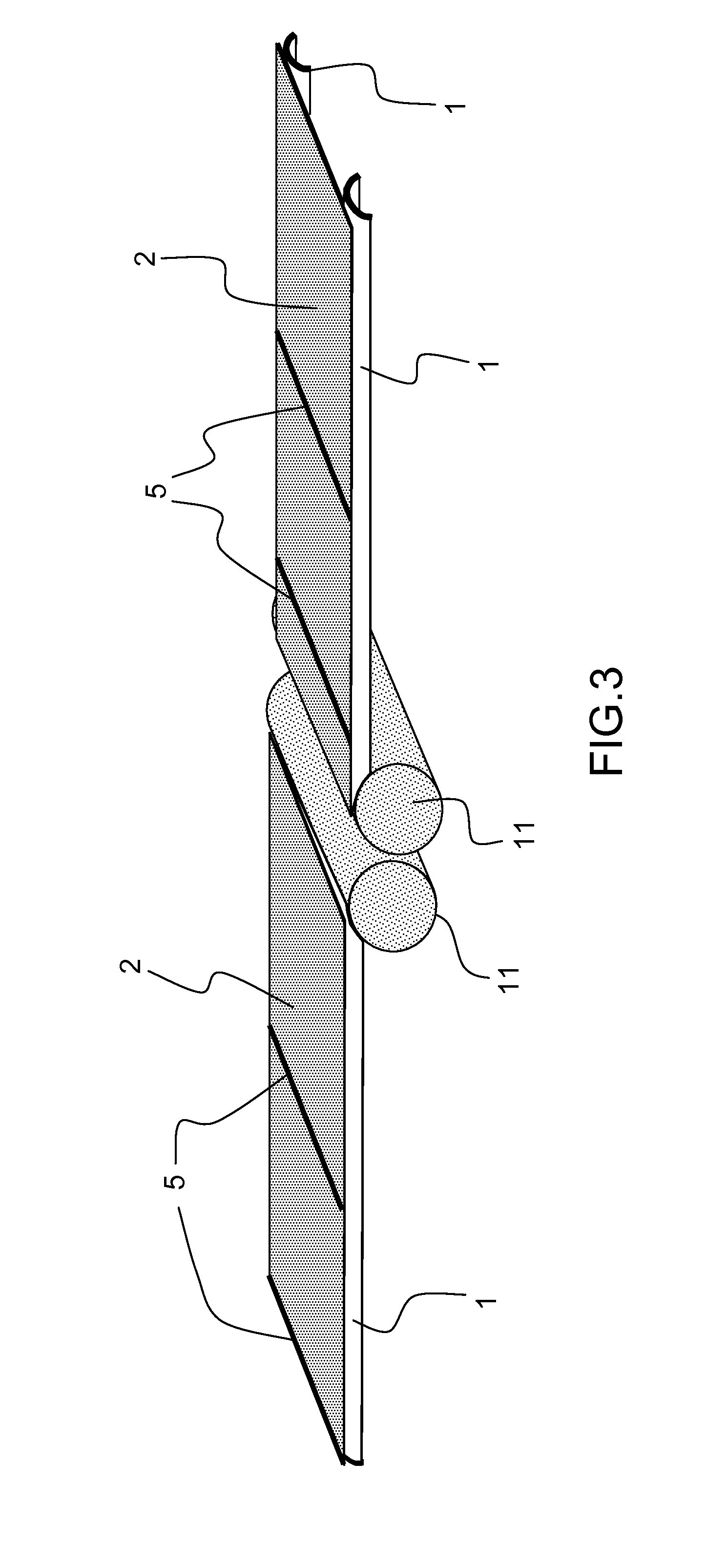
[0034]FIG. 2 shows a diagram of an example of a device according to the invention. The latter comprises a flexible membrane 2, supporting a plurality of photovoltaic cells, a plurality of tape-springs 1 constituting a bearing structure. Alternatively, said membrane 2 may be semi-rigid or composed of flexible and rigid elements such as thin, flat braces interlinked flexibly.

[0035]In the wound state, the tape-springs 1 are preferably wound around their natural radius of curvature. A mandrill 11 may be present, essentially to ensure the winding support function for the flexible membrane 2.

[0...


PUM


Abstract

A solar generator deployment device includes an assembly comprising a plurality of tape-springs supporting a windable membrane on a face of which is arranged a plurality of elements capable of converting the solar energy into electrical energy. The tape-springs and membrane are co-wound around a unique radius of curvature equal to the natural radius of curvature of folding of the tape-spring in the wound state. The tape-springs are substantially parallel and interlinked by transversal braces ensuring the rigidity of the bearing structure.

Description

CROSS-REFERENCE TO RELATED APPLICATION[0001]This application claims priority to foreign French patent application No. FR 1005184, filed on Dec. 30, 2010, the disclosure of which is incorporated by reference in its entirety.FIELD OF THE INVENTION[0002]The field of the invention is that of structures that are deployable in space that can advantageously be used for the deployment of solar generators.BACKGROUND[0003]Tape-springs are known as such in the space domain as being tapes capable of changing from the wound state to the unwound state essentially by virtue of their own elastic energy; in the unwound state, the known tape-springs generally exhibit a rigidity which is capable of maintaining them in that state.[0004]The conventional tape-springs, generally metallic, therefore have a natural tendency to unfold to return to their stable state. If they are forced to be folded back, they have a tendency to do so over a radius equal to that of their transversal radius of curvature. A wea...

Claims


Application Information

Patent Timeline
Patent Type & Authority Applications(United States)
IPC IPC(8): H01L31/045B65H16/00H02S30/20
CPCB64G1/222Y02E10/544B64G1/44
Inventor BLANCHARD, LAURENTDUCARNE, JULIENGEYER, FREDDYBAUDASSE, YANNICK
Owner THALES SA
Why Eureka
Try Eureka