High impact and load bearing solar glass for a concentrated large area solar module and method

a solar module and large area technology, applied in the field of solar energy techniques, can solve the problems of increasing energy consumption, still certain limitations, and high cost of solar cells, and achieve the effects of reducing the amount of glass material, reducing cost, and simplifying structur

Inactive Publication Date: 2012-07-05
SOLARIA CORP
View PDF4 Cites 45 Cited by
  • Summary
  • Abstract
  • Description
  • Claims
  • Application Information

AI Technical Summary

Benefits of technology

[0019]Many benefits can be achieved by ways of the present invention. For example, the present solar module provides a simplified structure for a manufacturing process. The solar module according to embodiments of the present invention eliminates the use of certain materials (e.g., acrylic) and reduces the amount of glass material for the concentrator structure. The present solar module may be fabricated using few process steps resulting in lower cost and improved product reliability due to less mismatch in thermal expansion coefficients of the materials.

Problems solved by technology

As the population of the world has increased, industrial expansion has led to a corresponding increased consumption of energy.
Although solar panels have been used successfully for certain applications, there are still certain limitations.
Solar cells are often costly.
Depending upon the geographic region, there are often financial subsidies from governmental entities for purchasing solar panels, which often cannot compete with the direct purchase of electricity from public power companies.
Additionally, the panels are often composed of costly photovoltaic silicon bearing wafer materials, which are often difficult to manufacture efficiently on a large scale, and sources can be limited.

Method used


Image

  • High impact and load bearing solar glass for a concentrated large area solar module and method
  • High impact and load bearing solar glass for a concentrated large area solar module and method
  • High impact and load bearing solar glass for a concentrated large area solar module and method

Examples


Embodiment Construction

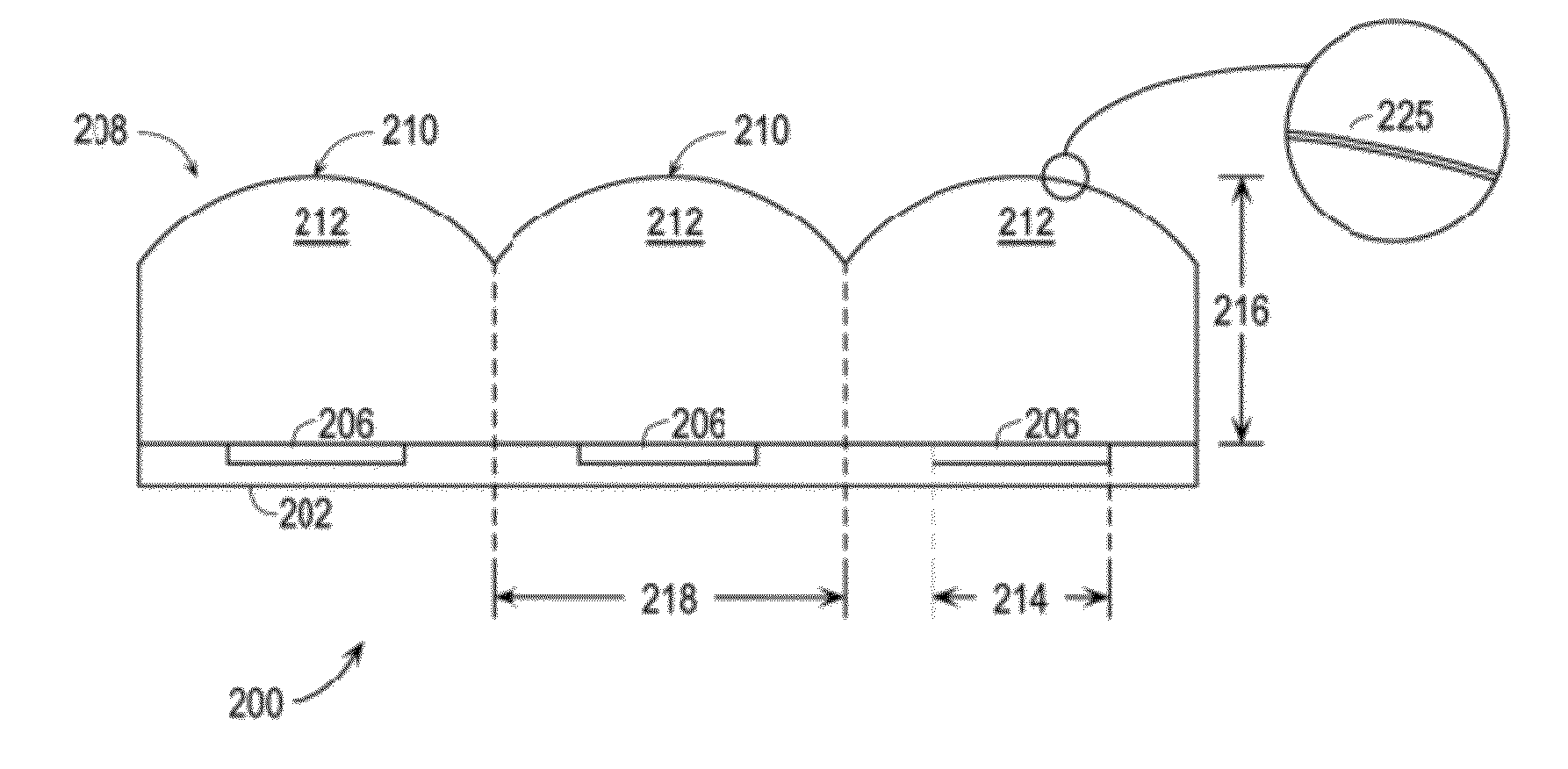
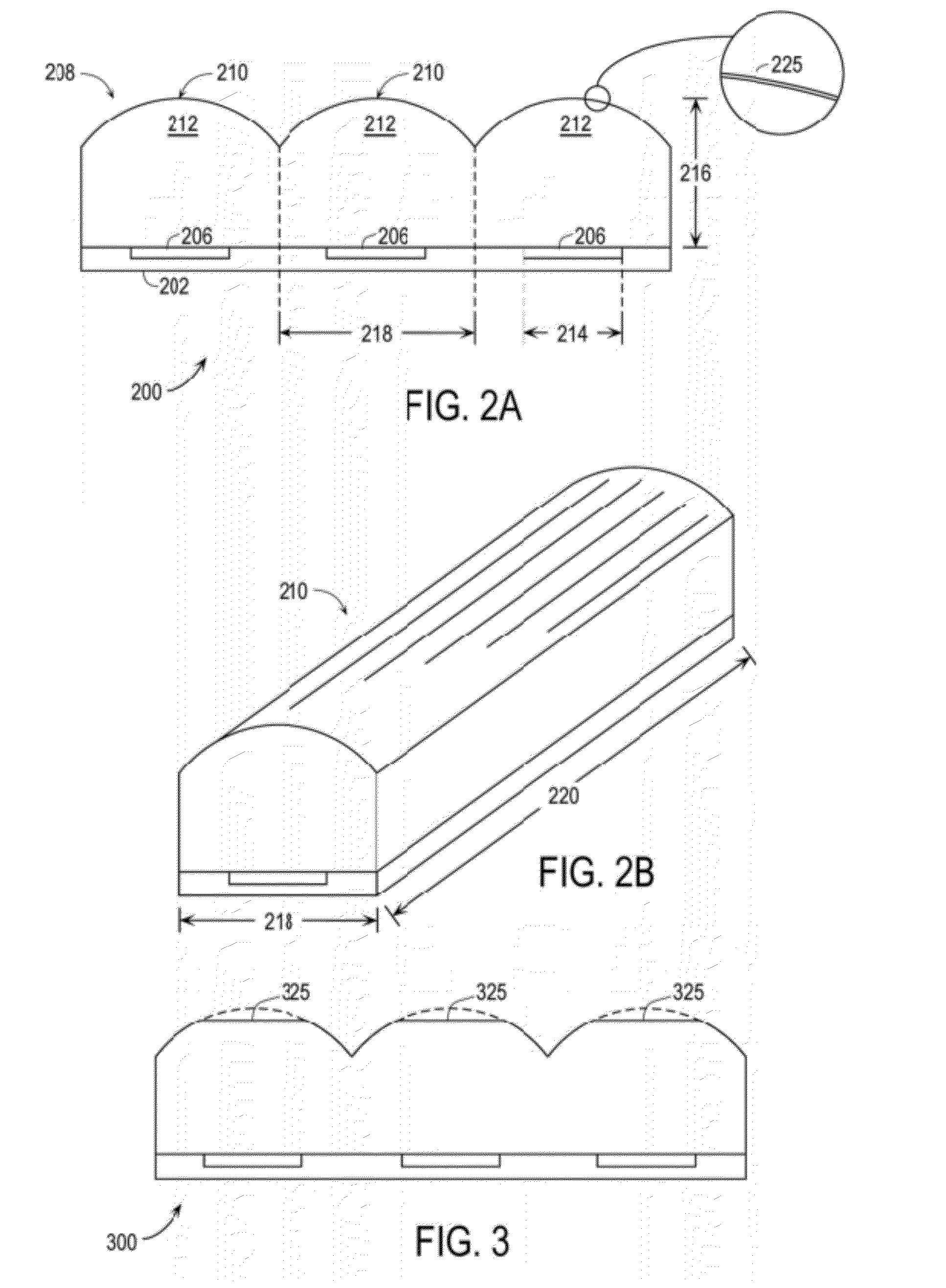
[0030]Embodiments of the present invention provide structures and fabrication methods for a solar module, such as might be applied to solar panels. More particularly, the present invention provides a high impact concentrated solar glass for a large area solar module. Embodiments of the present invention use concentrator elements to reduce the amount of photovoltaic material required, thereby reducing overall cost. It is noted that specific embodiments are shown for illustrative purposes, and represent examples. One skilled in the art would recognize other variations, modifications, and alternatives.

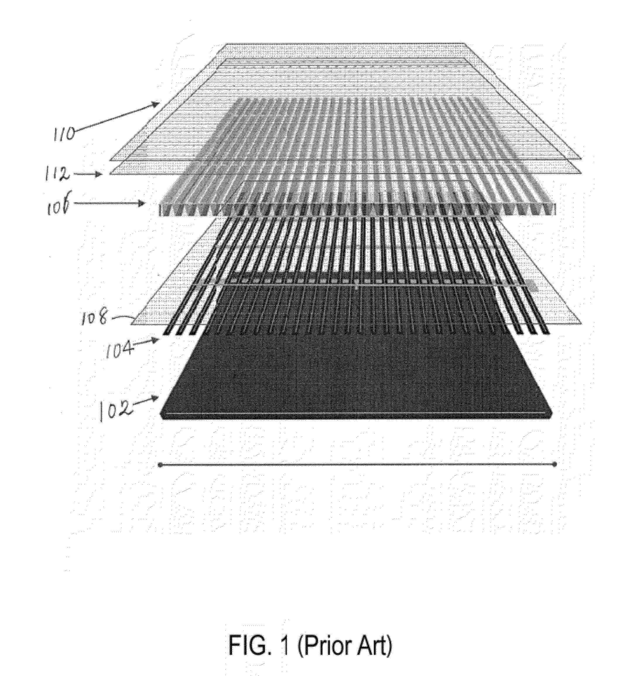
[0031]FIG. 1 is an exploded view of a conventional solar module 100. As shown, the conventional solar module includes, generally from back to front, the following elements: a back cover member 102; a plurality of photovoltaic strips 104 a plurality of elongate concentrator elements 106 aligned with and held to the photovoltaic strips by an optically clear adhesive 108; and a cover member ...


PUM


Abstract

A solar module device. The device has a substrate having a surface region. The device has one or more photovoltaic regions overlying the surface region of the substrate. In a preferred embodiment, each of the photovoltaic strips is derived from dicing a solar cell in to each of the strips. Each of the strips is a functional solar cell. The device also has an impact resistant glass member having a plurality of elongated concentrating elements spatially arranged in parallel configuration and operably coupled respectively to the plurality of elongated concentrating elements. Preferably, the impact resistant glass has a strength of at least 3× greater than a soda lime glass, e.g., conventional soda lime glass for conventional solar cells, e.g., a low iron soda lime glass. In a preferred embodiment, the impact resistant glass member comprises a planar region and a concentrator region comprising the plurality of elongated concentrating element spatially arranged in parallel configuration.

Description

CROSS-REFERENCES TO RELATED APPLICATIONS[0001]This application relates to co-pending, commonly owned U.S. patent application Ser. No. 12 / 687,862 filed Jan. 14, 2010 for “Solar Cell Concentrator Structure Including a Plurality of Glass Concentrator Elements With a Notch Design”, the entire disclosure of which is incorporated by reference for all purposes.BACKGROUND OF THE INVENTION[0002]The present invention relates generally to solar energy techniques, and in particular to a method and a structure for a resulting solar module. More particularly, the present invention provides a high impact concentrated solar glass for a large area solar module. Merely by way of example, the embodiments of the invention have been applied to solar panels, but it would be recognized that the invention has a much broader range of applicability.[0003]As the population of the world has increased, industrial expansion has led to a corresponding increased consumption of energy. Energy often comes from fossi...

Claims


Application Information

Patent Timeline
Patent Type & Authority Applications(United States)
IPC IPC(8): H01L31/052H01L31/0232
CPCY02E10/52Y02B10/12H01L31/0543H02S40/22
Inventor MAHESHWARI, ABHAYGIBSON, KEVIN R.
Owner SOLARIA CORP
Why Eureka
Try Eureka