Centrifugal-pendulum vibration absorbing device

Inactive Publication Date: 2012-07-05
AISIN AW CO LTD
View PDF17 Cites 14 Cited by
  • Summary
  • Abstract
  • Description
  • Claims
  • Application Information

AI Technical Summary

Benefits of technology

[0015]According to a sixth aspect of the present invention, the weight may be swingably coupled to the support member via an arm member. In addition, according to a seventh aspect of the present invention, a stopper portion that abuts against the arm member to prescribe a swing range of each of the mass bodies may be formed on the support member. Consequently, the stopper portion can be provided in a vacant space around the arm member without increasing the number of components.
[0016]According to an eighth aspect of the present invention, all of the plurality of mass bodies may have the same weight as each other, and the first mass body and the second mass body may have different structures from each other. In this case, every other mass body disposed on the support member has the same structure, and each mass body may be basically structured to be symmetric in the left-right direction. This allows each mass body to be well-balanced, which makes it possible to improve the vibration absorbing performance of the centrifugal-pendulum vibration absorbing device.
[0017]According to a ninth aspect of the present invention, all of the plurality of mass bodies may have the same structure and weight as each other. Providing all of the plurality of mass bodies with the same structure and weight as each other can reduce the number of types

Problems solved by technology

However, increasing the weight of each mass body of the centrifugal-pendulum vibration absorbing device basically inevitably increases the size of the mass bodies, and the increased size of the mass bodies reduces the clearance between mass bodies disposed adjacent to each other.
Therefore, in the case where the size of the mass bodies is increased

Method used


Image

  • Centrifugal-pendulum vibration absorbing device
  • Centrifugal-pendulum vibration absorbing device
  • Centrifugal-pendulum vibration absorbing device

Examples


Embodiment Construction

[0037]Now, an embodiment of the present invention will be described.

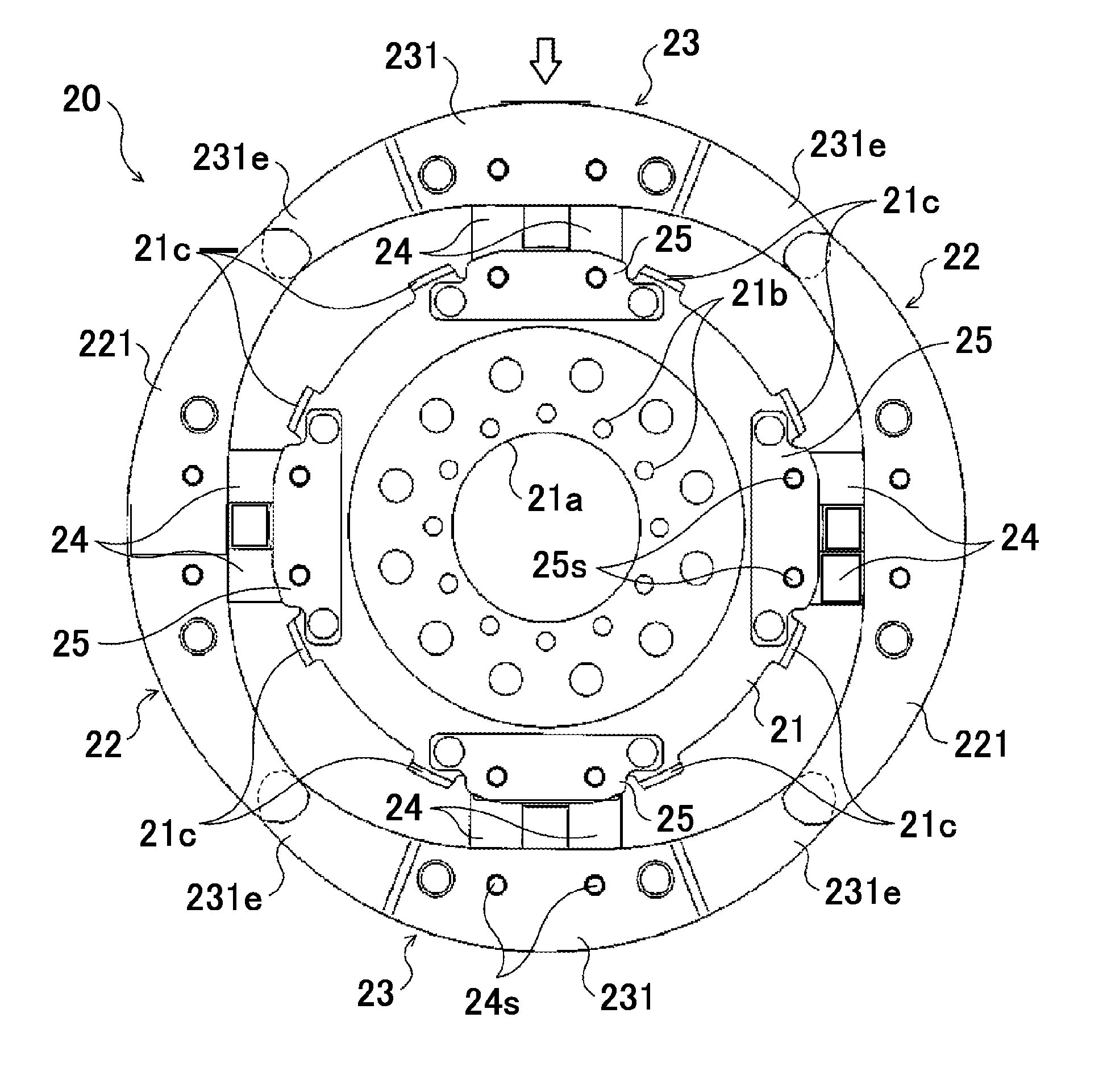
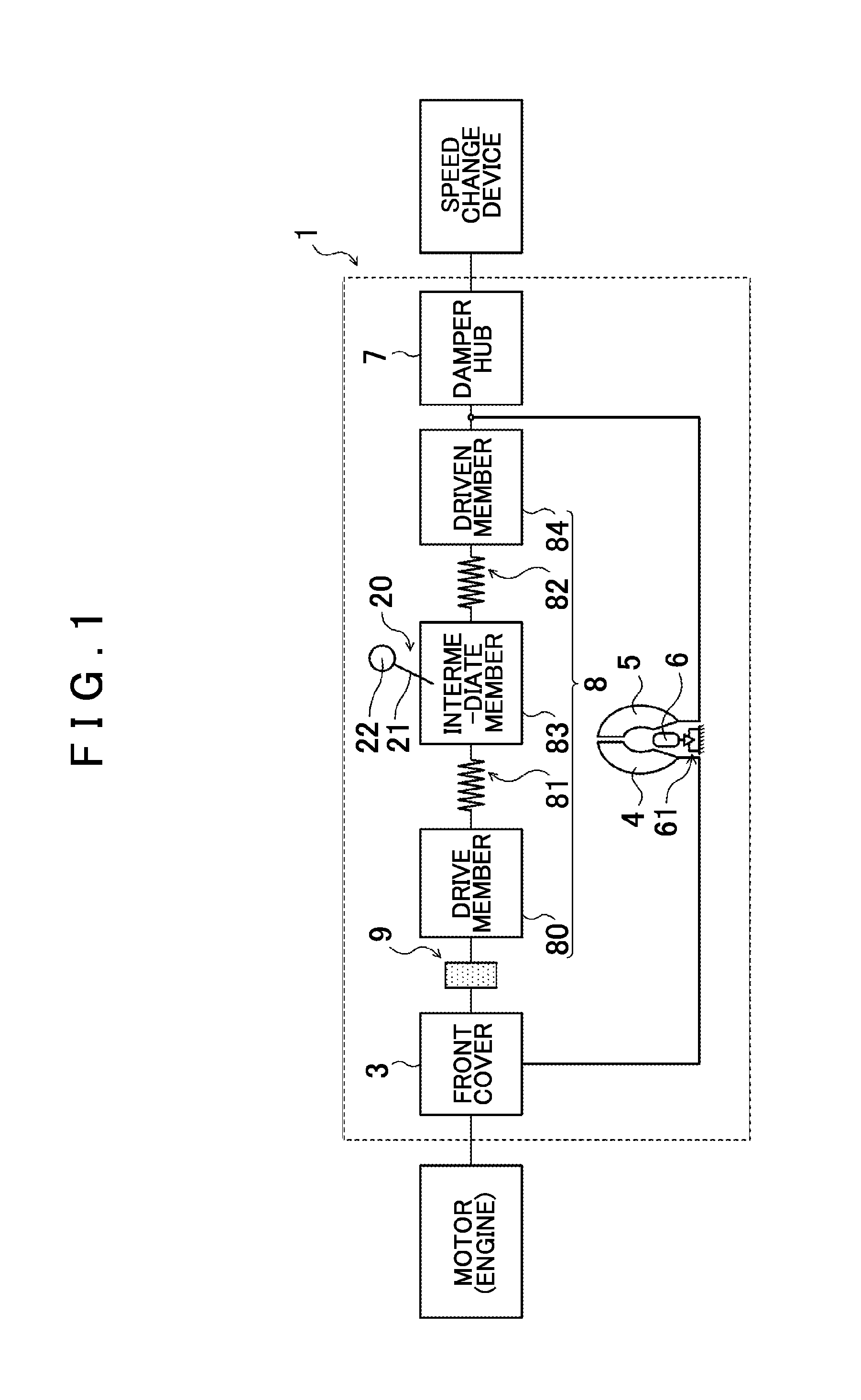
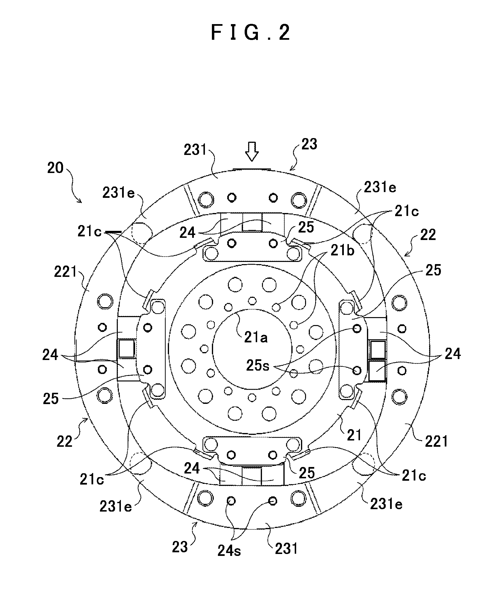
[0038]FIG. 1 shows a schematic configuration of a fluid transmission device 1 including a centrifugal-pendulum vibration absorbing device 20 according to an embodiment of the present invention. The fluid transmission device 1 shown in FIG. 1 is a torque converter mounted as a starting device on a vehicle including an engine (internal combustion engine) serving as a motor, and includes a front cover (input member) 3 coupled to a crankshaft (not shown) of the engine, a pump impeller (input-side fluid transmission element) 4 fixed to the front cover 3, a turbine runner (output-side fluid transmission element) 5 disposed coaxially with the pump impeller 4 so as to be rotatable, a stator 6 that rectifies a flow of working oil (working fluid) from the turbine runner 5 to the pump impeller 4, a damper hub (output member) 7 fixed to an input shaft of a speed change device which is an automatic transmission (AT) or a continu...


PUM


Abstract

A centrifugal-pendulum vibration absorbing device, including a member attached coaxially with a rotary element; and mass bodies swingably coupled to the support member and disposed adjacent to each other in a circumferential direction. The mass bodies are configured such that when a first mass body, which is one of two mass bodies disposed adjacent to each other, and a second mass body, which is the other of the two mass bodies, move with respect to the support member so as to approach each other, the first mass body and the second mass body overlap each other as seen from an axial direction of the rotary element.

Description

[0001]The disclosure of Japanese Patent Applications No. 2010-294401 filed on Dec. 29, 2010 and No. 2010-294404 filed on Dec. 29, 2010 including the specification, drawings and abstract is incorporated herein by reference in its entirety.BACKGROUND OF THE INVENTION[0002]1. Field of the Invention[0003]The present invention relates to a centrifugal-pendulum vibration absorbing device including a support member attached coaxially with a rotary element and a plurality of mass bodies swingably coupled to the support member and disposed adjacent to each other in the circumferential direction.[0004]2. Description of the Related Art[0005]Hitherto, there has been known a centrifugal-pendulum vibration absorbing device including a support member attached coaxially with a turbine runner of a fluid transmission device and a plurality of pendulum masses (mass bodies) each coupled to the support member via a support roller so as to be swingable with respect to the support member (see German Paten...

Claims


Application Information

Patent Timeline
IPC IPC(8): F16F7/10
CPCF16F15/145F16H45/02Y10T74/2128Y10T464/50F16H2045/0263F16F15/10
Inventor TAKIKAWA, YOSHIHIROMARUYAMA, KAZUTOITOU, KAZUHIROMAEDA, KOJI
Owner AISIN AW CO LTD
Why Eureka
Try Eureka