Impact penetrometer systems for characterizing soil properties

Active Publication Date: 2012-07-12
HONEYBEE ROBOTICS
View PDF3 Cites 5 Cited by
  • Summary
  • Abstract
  • Description
  • Claims
  • Application Information

AI Technical Summary

Benefits of technology

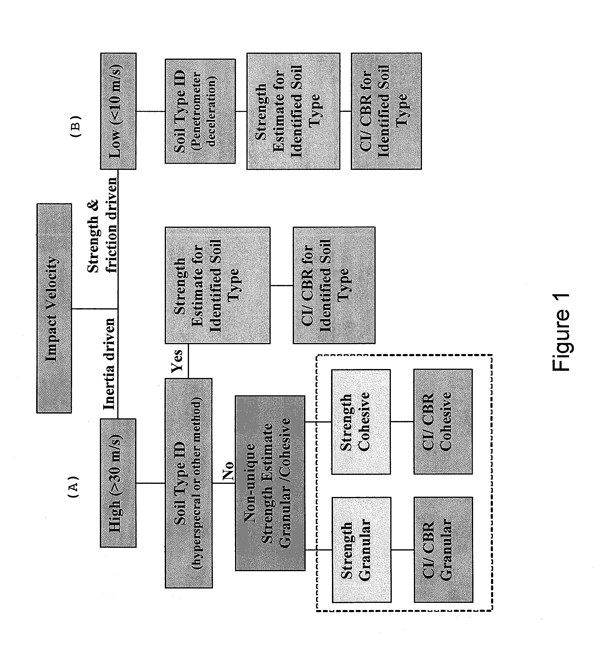
[0012]The deceleration data from both the high-velocity and low-velocity impacts can be packetized and transmitted to a base of operations using a satellite communications module built into the penetrometer systems. Onboard data processing and instantaneous go/no-go decision making is not required but can be implemented if the requirements change. The high-velocity (>30 m/s) penetrometer impact data will provide crude knowledge of the soil strength but will provide information about soil density, while the low-velocity (<10 m/s) penetrometer impact data will provide much more accurate knowledge of soil strength. The dual systems approach subst

Problems solved by technology

Prior aerial drop penetrometers achieved uncontrolled high velocities during impact or required parachutes to slow their decent.
High velocity impact resulted in penetrometer deceleration that was primarily caused by soil inertia, not soil strength.
At such high impact velocities, it become

Method used


Image

  • Impact penetrometer systems for characterizing soil properties
  • Impact penetrometer systems for characterizing soil properties
  • Impact penetrometer systems for characterizing soil properties

Examples


Embodiment Construction

[0024]In the following detailed description of the invention, certain preferred embodiments are illustrated providing certain specific details of their implementation. However, it will be recognized by one skilled in the art that many other variations and modifications may be made given the disclosed principles of the invention.

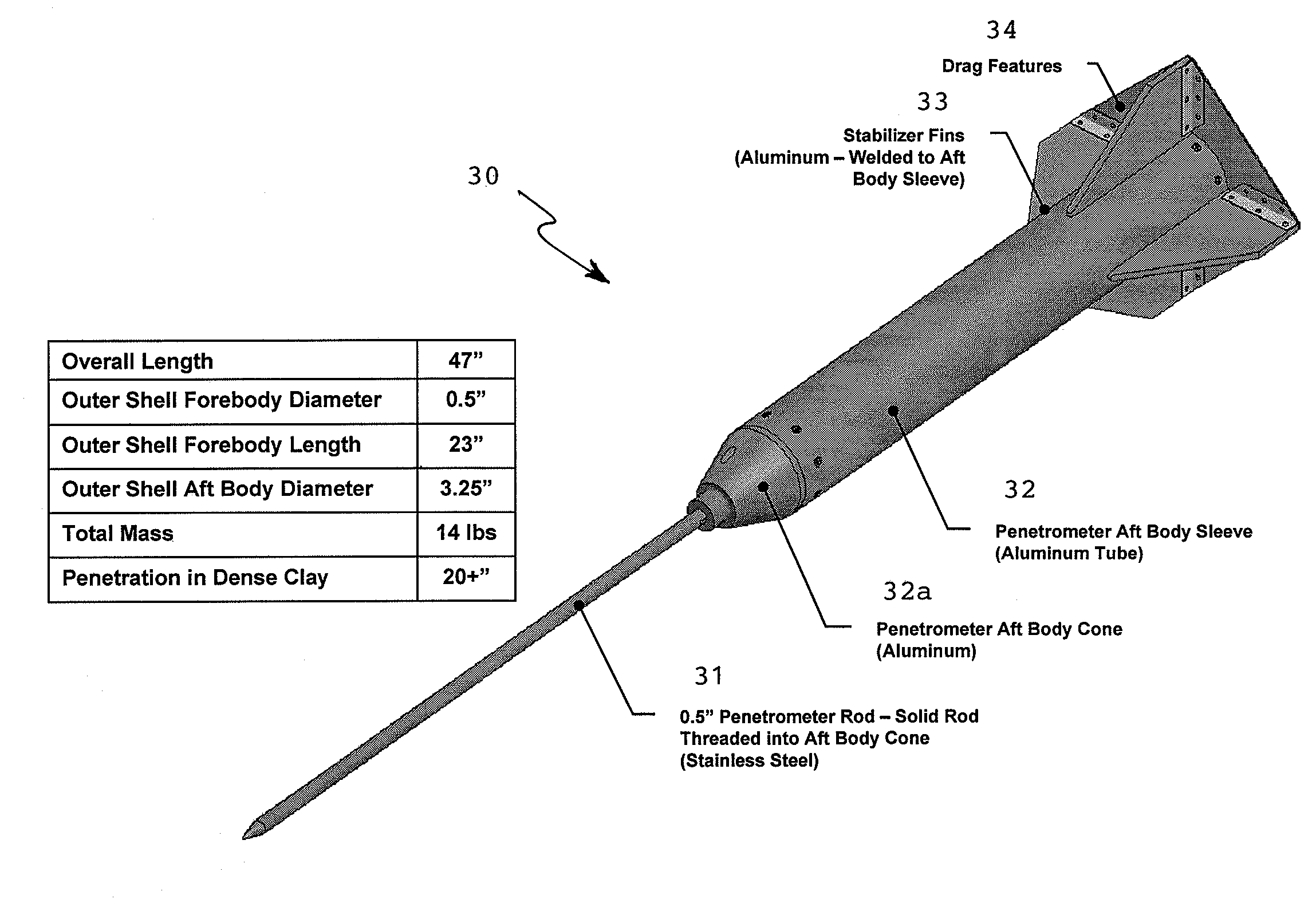
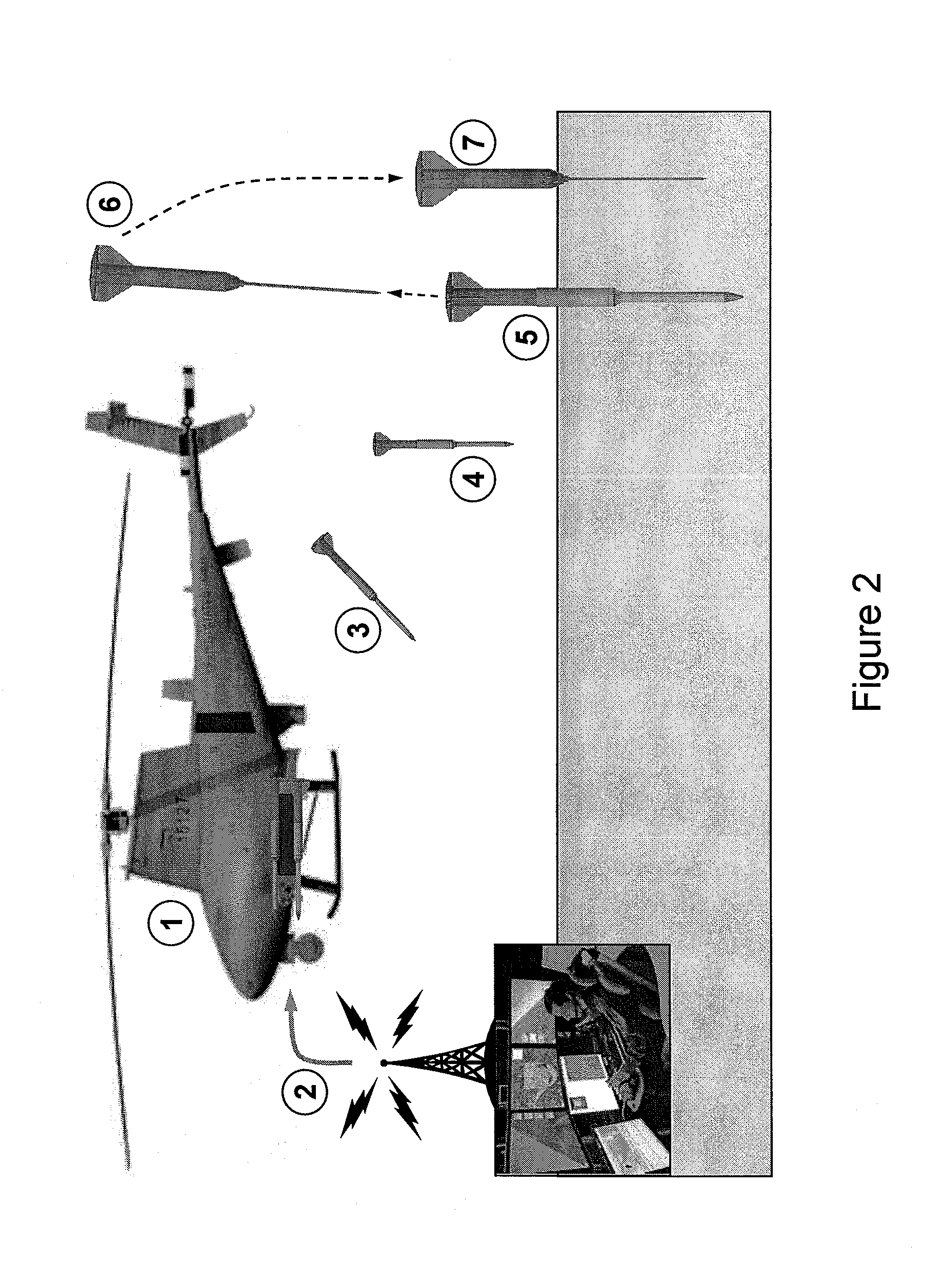
[0025]In accordance with the present invention, a dual aerial-drop penetrometer system includes a high speed (>30 m / s) penetrometer aerial unit combined with a low speed (<10 m / s) penetrometer aerial unit. Both penetrometers provide deceleration information as they penetrate the soil of interest. The data from the two penetrometers, after analysis, can be used to assess soil strength as well as trafficability for the deployment of remotely-controlled vehicles, for example.

[0026]From an understanding of information to be determined from the dual-impact, penetrometer deceleration data, a decision tree analysis flow chart is shown in FIG. 1 to derive the desired...


PUM


Abstract

A dual aerial-drop penetrometer system includes a high-velocity (>30 m/s) penetrometer aerial unit combined with a low-velocity (<10 m/s) penetrometer aerial unit. The primary penetrometer is formed as an outer shell having the secondary penetrometer received in telescoping fashion within, which is ejected by a spring ejection mechanism upon impact of the outer shell. Both penetrometers provide deceleration information as they penetrate the soil of interest. The data from the two penetrometers, after analysis, can be used to assess soil strength as well as trafficability for the deployment of remotely-controlled vehicles, for example.

Description

[0001]This U.S. patent application claims the priority filing date of U.S. Provisional Application No. 61 / 383,992, filed on Sep. 17, 2010, entitled “Impact Penetrometer Systems for Characterizing Soil Properties”.[0002]The subject matter of this U.S. patent application was developed under a grant obtained through the Department of Defense SBIR Phase I program, Contract No. N0001409M0227, administered through the Office of Naval Research. The U.S. Government retains certain rights in the invention.FIELD OF INVENTION[0003]The present invention relates to a method and systems for to remotely determine soil strength and trafficability, and particularly to aerial drop penetrometer systems.BACKGROUND OF INVENTION[0004]Prior aerial drop penetrometers achieved uncontrolled high velocities during impact or required parachutes to slow their decent. High velocity impact resulted in penetrometer deceleration that was primarily caused by soil inertia, not soil strength. Soil inertia is a functio...

Claims


Application Information

Patent Timeline
IPC IPC(8): G01N3/42
CPCG01N3/48B33Y80/00
Inventor JOHNSON, JEROMEZACNY, KRISCHU, PHILIP
Owner HONEYBEE ROBOTICS
Why Eureka
Try Eureka