Passive magnetic bearing system

a magnetic bearing and passive technology, applied in the direction of bearings, shafts and bearings, dynamo-electric machines, etc., to achieve the effect of minimizing current and improving the stabilizer for displacemen

Inactive Publication Date: 2012-07-12
LAWRENCE LIVERMORE NAT SECURITY LLC
View PDF2 Cites 25 Cited by
  • Summary
  • Abstract
  • Description
  • Claims
  • Application Information

AI Technical Summary

Benefits of technology

[0010]The invention pertains to improved versions of passive magnetic bearings of the types described in previous Lawrence Livermore National Laboratory (LLNL) patents such as U.S. Pat. No. 5,847,480, incorporated herein by reference and U.S. Pat. No. 5,495,223, incorporated herein by reference. The improvements include embodiments of a re-designed axial stabilizer; one with provision for external control of its stiffness through switching in external inductances, for example. External control also allows the stabilizer to become a part of a passive/active magnetic bearing system; one that requires no external source of power and no position sensor, since it operates by sensing the voltage generated in its stabilizer windings and responds by using electronic switches to control the current that flows in the windings. The invention also provides embodiments of an improved stab...

Problems solved by technology

Since such a system is unstable when at rest, means are provided ...

Method used


Image

  • Passive magnetic bearing system
  • Passive magnetic bearing system
  • Passive magnetic bearing system

Examples


Embodiment Construction

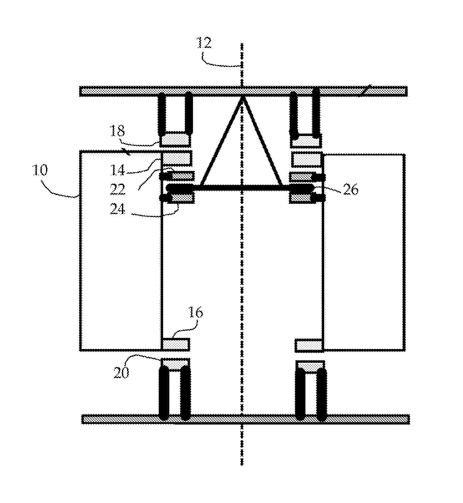
[0019]The invention is concerned with satisfying constraints on passive magnetic bearing systems that may be associated with a particular application. Examples of such constraints are applications where the positive stiffness requirements may vary during operation of the system. An example would be a flywheel system to be used in a vehicle. When the vehicle is at rest the net positive stiffness need only be sufficient to insure stability of the EMB rotor in the absence of accelerations. The stabilizer can thus be designed to minimize the resistive losses in the windings when in the standby mode, thus allowing long self-discharge times. When the vehicle is in motion, however, the stabilizer stiffness must be increased to maintain centering under the accelerations that are encountered. In stationary applications, it may be desirable to find a simple means to “tune” the levitation magnet / stabilizer system to minimize its power losses.

[0020]Some embodiments of the new invention include ...


PUM


Abstract

An axial stabilizer for the rotor of a magnetic bearing provides external control of stiffness through switching in external inductances. External control also allows the stabilizer to become a part of a passive/active magnetic bearing system that requires no external source of power and no position sensor. Stabilizers for displacements transverse to the axis of rotation are provided that require only a single cylindrical Halbach array in its operation, and thus are especially suited for use in high rotation speed applications, such as flywheel energy storage systems. The elimination of the need of an inner cylindrical array solves the difficult mechanical problem of supplying support against centrifugal forces for the magnets of that array. Compensation is provided for the temperature variation of the strength of the magnetic fields of the permanent magnets in the levitating magnet arrays.

Description

STATEMENT REGARDING FEDERALLY SPONSORED RESEARCH OR DEVELOPMENT[0001]The United States Government has rights in this invention pursuant to Contract No. DE-AC52-07NA27344 between the United States Department of Energy and Lawrence Livermore National Security, LLC.BACKGROUND OF THE INVENTION[0002]1. Field of the Invention[0003]The present invention relates to magnetic bearing systems, and more specifically, it relates to axial and transverse stabilizers for such systems.[0004]2. Description of Related Art[0005]Passive magnetic bearing systems developed at Lawrence Livermore National Laboratory (LLNL) have been described in several U.S. patents, e.g., U.S. Pat. No. 5,495,223 “Dynamically Stable Magnetic Suspension System,” and U.S. Pat. No. 5,847,480, “Passive Magnetic Bearing Element with Minimal Power Losses.” Studies now underway at the LLNL address two special applications of flywheel energy storage in modular electromechanical batteries (EMBs). The first of these is the bulk stora...

Claims


Application Information

Patent Timeline
IPC IPC(8): H02K7/09
CPCF16C32/0436F16C2361/55F16C32/0448
Inventor POST, RICHARD F.
Owner LAWRENCE LIVERMORE NAT SECURITY LLC
Why Eureka
Try Eureka