Organic Light Emitting Display Apparatus and Method of Manufacturing the Same

a technology of light-emitting display and organic materials, which is applied in the manufacture of electric discharge tubes/lamps, instruments, discharge tubes luminescnet screens, etc., can solve the problems of reducing productivity and preventing high-resolution, and achieve the effect of reducing the distance between deposited patterns and improving productivity

Active Publication Date: 2012-07-12
SAMSUNG DISPLAY CO LTD
View PDF2 Cites 42 Cited by
  • Summary
  • Abstract
  • Description
  • Claims
  • Application Information

AI Technical Summary

Benefits of technology

[0029]In the organic light emitting display apparatus, three-colored emission layers may be formed using two mask processes so that productivity may be improved due to process simplification, and high-resolution maybe realized due to a decrease in the distance between deposited patterns.

Problems solved by technology

Then, the mask processes increase, and thus productivity may be reduced.
Thus, an increase in the mask processes causes an obstruction for realizing high resolution.

Method used


Image

  • Organic Light Emitting Display Apparatus and Method of Manufacturing the Same
  • Organic Light Emitting Display Apparatus and Method of Manufacturing the Same
  • Organic Light Emitting Display Apparatus and Method of Manufacturing the Same

Examples


Embodiment Construction

[0036]Hereinafter, one or more embodiments of the present invention will be described in detail with reference to the accompanying drawings.

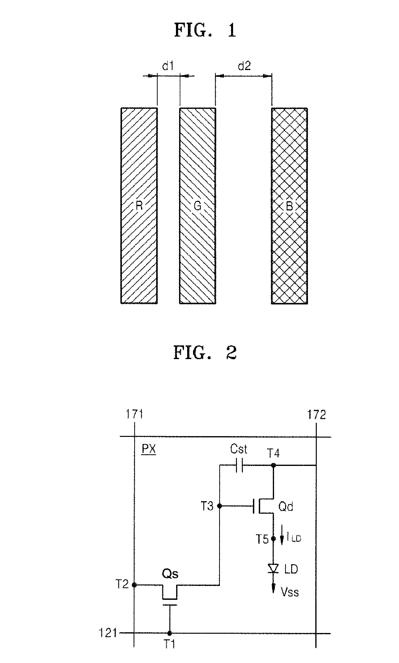
[0037]FIG. 1 is a plan view schematically illustrating a unit pixel of an organic light emitting display apparatus according to an embodiment of the present invention.

[0038]More specifically, FIG. 1 illustrates three colors of sub pixels forming a unit pixel of an organic light emitting display apparatus according to an embodiment of the present invention.

[0039]Referring to FIG. 1, the unit pixel includes three colors of sub pixels such as a red (R) sub pixel, a green (G) sub pixel, and a blue (B) sub pixel. In the organic light emitting display apparatus, unit pixels including the three colors of sub pixels are repeatedly arranged along row and column directions.

[0040]In the latter regard, a distance d1 between the red (R) sub pixel and the green (G) sub pixel may be shorter than a distance d2 between the blue (B) sub pixel and the green (G) su...


PUM


Abstract

An organic light emitting display apparatus using a micro cavity method comprises a first sub pixel, a second pixel and a third pixel, each of which emits different color from an emission layer interposed between two electrodes. The first sub pixel, the second sub pixel and the third sub pixel form a unit pixel. Emission layers of the first and second sub pixels are formed so as to have the same pattern throughout the first and second sub pixels, and an emission layer of the third sub pixel is formed so as to have a pattern separate from the first and second sub pixels. In this structure, three-colored emission layers may be formed using two mask processes so that productivity is improved due to process simplification, and high-resolution is realized due to a decrease in the distance between deposited patterns.

Description

CLAIM OF PRIORITY[0001]This application makes reference to, incorporates the same herein, and claims all benefits accruing under 35 U.S.C. §119 from an application earlier filed in the Korean Intellectual Property Office on Jan. 10, 2011 and there duly assigned Serial No. 10-2011-0002304.BACKGROUND OF THE INVENTION[0002]1. Field of the Invention[0003]The present invention relates to an organic light emitting display apparatus, and more particularly, to an organic light emitting display apparatus which is improved by reducing the number of uses of a mask when manufacturing an emission layer, and a method of manufacturing the same.[0004]2. Description of the Related Art[0005]In general, organic light emitting display apparatuses have wide viewing angles, excellent contrast, and rapid response speed relative to other display apparatus.[0006]The organic light emitting display apparatus may realize a color in such a way that holes injected from an anode and a cathode are recombined in an...

Claims


Application Information

Patent Timeline
Patent Type & Authority Applications(United States)
IPC IPC(8): H01L27/32H01J9/14
CPCH01L27/3206H01L27/3211H01L2227/323H01L51/5265H01L51/5036H10K59/30H10K59/35H10K50/125H10K50/852H10K59/1201G02B5/201H10K59/352H10K59/131H10K50/814H10K50/824
Inventor LEE, SUNG-SOOCHU, CHANG-WOONGKIM, SE-IL
Owner SAMSUNG DISPLAY CO LTD
Why Eureka
Try Eureka