Method and Apparatus for Amplifying and Dynamically Adjusting Optical Signal

a dynamic adjustment and optical signal technology, applied in electrical apparatus, lasers, laser details, etc., can solve the problems of more obvious problems and complex onu hardware, and achieve the effect of reducing the complexity of onu and olt devices and reducing the agc adjustment rang

Active Publication Date: 2012-07-12
ZTE CORP
View PDF5 Cites 21 Cited by
  • Summary
  • Abstract
  • Description
  • Claims
  • Application Information

AI Technical Summary

Benefits of technology

[0053]The method and apparatus for amplifying and dynamically adjusting an uplink optical signal in a PON network provided by the present invention implement amplification and output power equalization on uplink burst optical signals of different ONUs through dynamically adjusting a control signal loaded on an optical amplifier by a gain control circuit according to real-time detection results of the uplink signal in a trunk fiber link, which can effectively reduce an AGC adjustment range at an OLT side, reduce the complexity of the ONU and the OLT devices, and can also make the input optical power of the wavelength converter always remain within the linear working area.

Problems solved by technology

And the next generation PON network with a higher rate will require shorter AGC time, and therefore, this problem will be more obvious.
Although requirements on the AGC adjustment range of the OLT receiver are relaxed through the adjustment mechanism, this makes the ONU hardware more complex, and it is needed to add related control protocols between the OLT and the ONU.

Method used


Image

  • Method and Apparatus for Amplifying and Dynamically Adjusting Optical Signal
  • Method and Apparatus for Amplifying and Dynamically Adjusting Optical Signal
  • Method and Apparatus for Amplifying and Dynamically Adjusting Optical Signal

Examples


Embodiment Construction

[0065]The technical scheme will be further described in detail in conjunction with accompanying drawings and specific embodiments hereinafter.

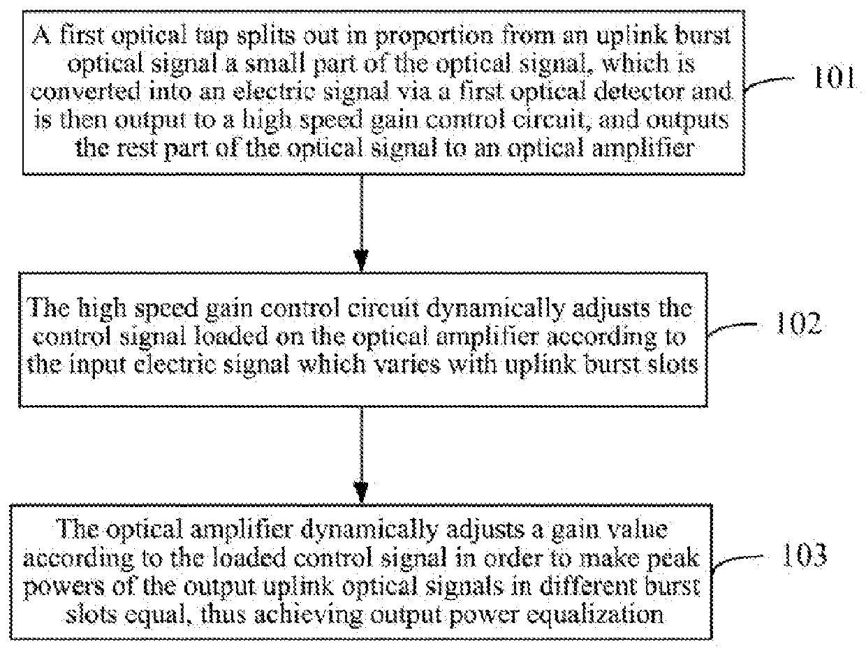
[0066]If a relay amplifier used in an uplink of a long-distance PON can make output power of uplink burst optical signals in different slots equal while amplifying the signals, i.e., making peak powers of the uplink burst optical signals in different slots received by the OLT close or equal, which can significantly reduce the technical difficulty of the OLT gain adjustment without adding an additional output power adjustment module within the ONU, and significantly reduce the cost of the device.

[0067]As the downlink signals of the current PON and the next generation PON (10G-EPON and NG-EPON) are planned respectively in the S band (approximately 1490 nm) and L band (approximately 1580 nm). The L band belongs to the gain wavelength range of an Erbium Doped Fiber Amplifier (EDFA), so the use of EDFA is more appropriate; the amplification in S ba...


PUM


Abstract

A method for amplifying and dynamically adjusting an optical signal is provided in the present invention, which includes: a first optical tap splitting out a small part of the optical signal, which is converted into an electric signal via a first optical detector and is then output to a high speed gain control circuit, in proportion from an uplink burst optical signal, and outputting a remainder of the optical signal to an optical amplifier; the high speed gain control circuit dynamically adjusting the control signal loaded on the optical amplifier according to the input electric signal which varies with uplink burst slots; and the optical amplifier dynamically adjusting a gain value according to the loaded control signal to make peak powers of the output uplink optical signals in different burst slots equal, thus achieving output power equalization.

Description

TECHNICAL FIELD[0001]The present invention relates to the field of optical access network communications, and in particular, to a method and apparatus for amplifying and dynamically adjusting an optical signal in a long-distance passive optical network.BACKGROUND OF THE RELATED ART[0002]The Passive Optical Network (PON) technology with the advantages of low-cost, multi-user access, ultra-long distance transmission, high transmission bandwidth etc., has gradually replaced the existing cable access network with the copper wire as a transmission medium, and becomes the mainstream broadband access network technology. At present, there are mainly two PON technologies, i.e., the Ethernet Passive Optical Network (EPON) and the Gigabit-Capable Passive Optical Network (GPON). Generally, the coverage of both PONs is 20 km, and the maximum branching ratio is 1:64 or 1:128. The maximum transmission distance and the splitting ratio are mainly limited by optical power budget of the PON network, w...

Claims


Application Information

Patent Timeline
Patent Type & Authority Applications(United States)
IPC IPC(8): H01S5/20H04B10/294
CPCH04B10/2942
Inventor HE, ZIANSU, JIEZHU, SONGLIN
Owner ZTE CORP
Why Eureka
Try Eureka