Method and apparatus optimizing decision threshold level of optical receiver

a decision threshold and optical receiver technology, applied in the field of optical communication, can solve the problems of complex influence of these factors on the numeric values of bit errors b>0/b> and b>1/b>, affecting the normal communication of services, and affecting the performance of signals. , to achieve the effect of simple implementation and avoid shock phenomena

Active Publication Date: 2011-07-28
ZTE CORP
View PDF9 Cites 5 Cited by
  • Summary
  • Abstract
  • Description
  • Claims
  • Application Information

AI Technical Summary

Benefits of technology

[0026]Using the technical scheme of the present invention allows to reduce firstly the adjustment range of the decision threshold and decrease the adjustment step of the decision threshold after the services are activated, and then optimize and adjust the decision threshold of the optical receiver based on the pre-FEC BERs to obtain the optimal decision threshold value after the adjustment range of the decision threshold is reduced.
[0027]Compared with the prior art, the present invention is simple to implement, avoiding shock phenomena caused when the optical receiver adjusts the decision threshold frequently in a large range in service bearing working condition.

Problems solved by technology

However, distortion may be caused in the signals 1 and 0 due to the influence of factors, such as noise and non-linear effect of optical fibers, in the process of long-distance transmission, therefore, the decision threshold of the optical receiver is required to be adjusted to accurately decide the signals 0 and 1.
The influence of these factors on numeric values of bit errors 0 and 1 is complicated.
When certain factors change suddenly due to the influence of the external environment on the system, using the above method to adjust the decision threshold in real time may cause large-range adjustment and shock of the decision threshold, thus resulting in performance deterioration of signals, or affecting normal communication of services in severe case.
It can be seen that the above method of adjusting the decision threshold in real time in a large range during operation of the optical receiver has a risk of affecting the stability and reliability of the system.

Method used


Image

  • Method and apparatus optimizing decision threshold level of optical receiver
  • Method and apparatus optimizing decision threshold level of optical receiver
  • Method and apparatus optimizing decision threshold level of optical receiver

Examples


Embodiment Construction

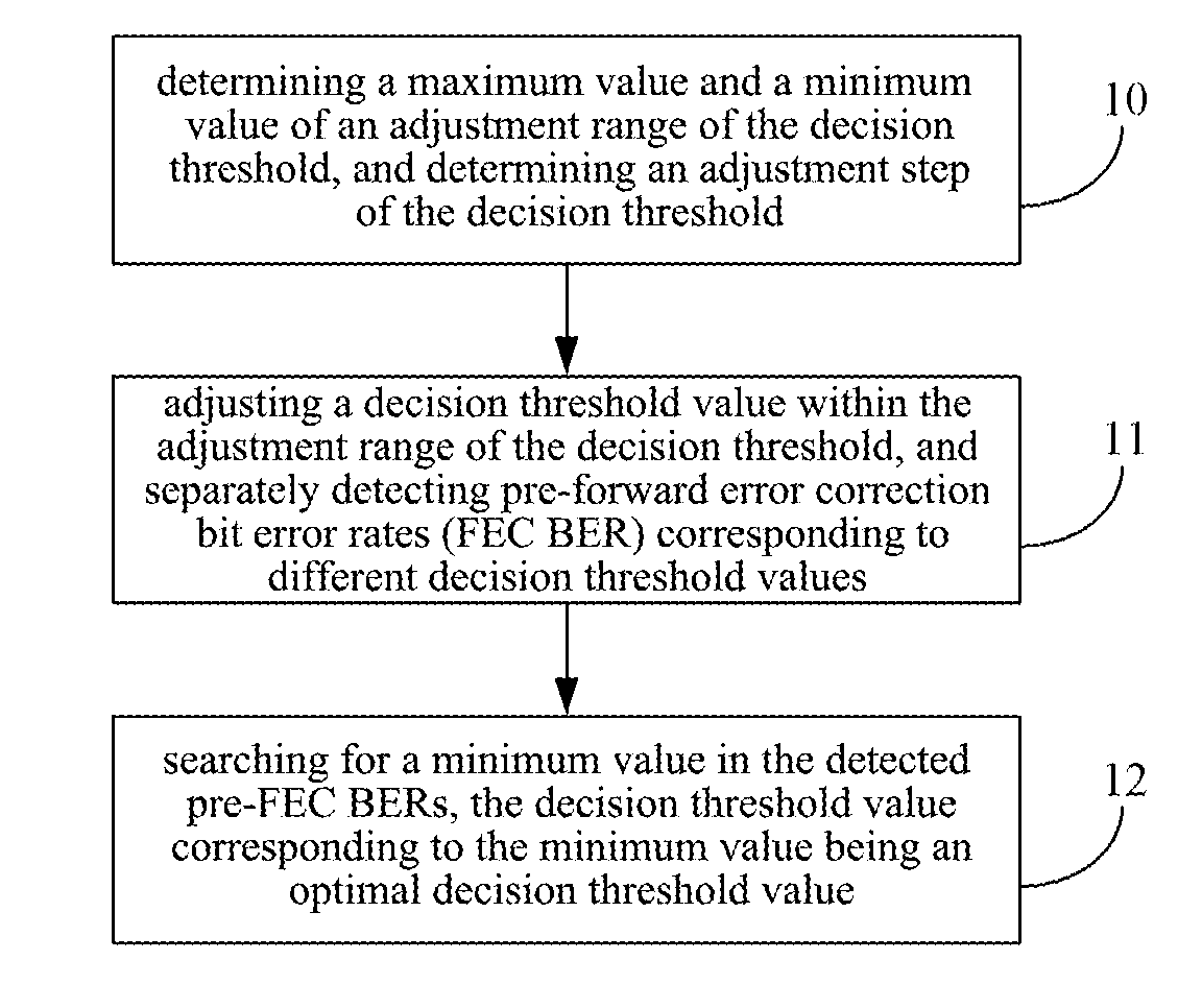
[0032]Referring to FIG. 1, there is provided a flow chart of an implementation principle of a method for optimizing a decision threshold of an optical receiver in accordance with the present invention mainly comprising the following step.

[0033]Step 10, a maximum value and a minimum value of an adjustment range of the decision threshold are determined, and an adjustment step of the decision threshold is determined.

[0034]The method further comprises, prior to the above step, determining system parameters of the optical receiver to be within a proper range and be kept unchanged. The system parameters of the optical receiver include received optical power, optical signal-to-noise ratio, and residual dispersion.

[0035]Step 11, a decision threshold value is adjusted within the adjustment range of the decision threshold, and pre-forward error correction bit error rates corresponding to different decision threshold values are detected separately, wherein the pre-FEC BER is a sum of the numbe...


PUM


Abstract

method and apparatus for optimizing a decision threshold of an optical receiver is used to solve a problem of affecting system stability and reliability. The method comprises: determining a maximum value and a minimum value of an adjustment range of the decision threshold, and determining an adjustment step of the decision threshold (10); adjusting a decision threshold value within the adjustment range of the decision threshold, and separately detecting pre-FEC BERs corresponding to different decision threshold values (11); and searching for a minimum value in the detected pre-FEC BERs, a decision threshold value corresponding to the minimum value being an optimal decision threshold value (12). The apparatus comprises a decision threshold adjusting unit, a pre-FEC BER detecting unit, a decision threshold control unit and an optimal decision threshold determining unit.

Description

TECHNICAL FIELD[0001]The present invention relates to the technical field of optical communication, and more particular, to a method and an apparatus for optimizing a decision threshold of an optical receiver.TECHNICAL BACKGROUND[0002]In an optical communication system, an optical transmitter at a transmitting end converts digital electrical signals of 0 and 1 into optical signals to be transmitted in optical fibers, and an optical receiver at a receiving end restores the optical signals to the digital electrical signals of 0 and 1 through photoelectric conversion. Ideally, a decision threshold of the optical receiver is at an average value, i.e., 50%, such that the signals of 0 and 1 can be accurately decided. However, distortion may be caused in the signals 1 and 0 due to the influence of factors, such as noise and non-linear effect of optical fibers, in the process of long-distance transmission, therefore, the decision threshold of the optical receiver is required to be adjusted ...

Claims


Application Information

Patent Timeline
Patent Type & Authority Applications(United States)
IPC IPC(8): H04B10/06H04B17/00H04B10/43
CPCH04B10/695H04B10/60H03M13/03
Inventor PENG, XIAO
Owner ZTE CORP
Why Eureka
Try Eureka