Source and multiple loads regulator

Inactive Publication Date: 2012-07-12
BRAXTON ENG
View PDF5 Cites 69 Cited by
  • Summary
  • Abstract
  • Description
  • Claims
  • Application Information

AI Technical Summary

Benefits of technology

[0058]the load group current through at least one load group is established throughout most of an Alternating Current (AC) line cycle commensurate with power requirements

Problems solved by technology

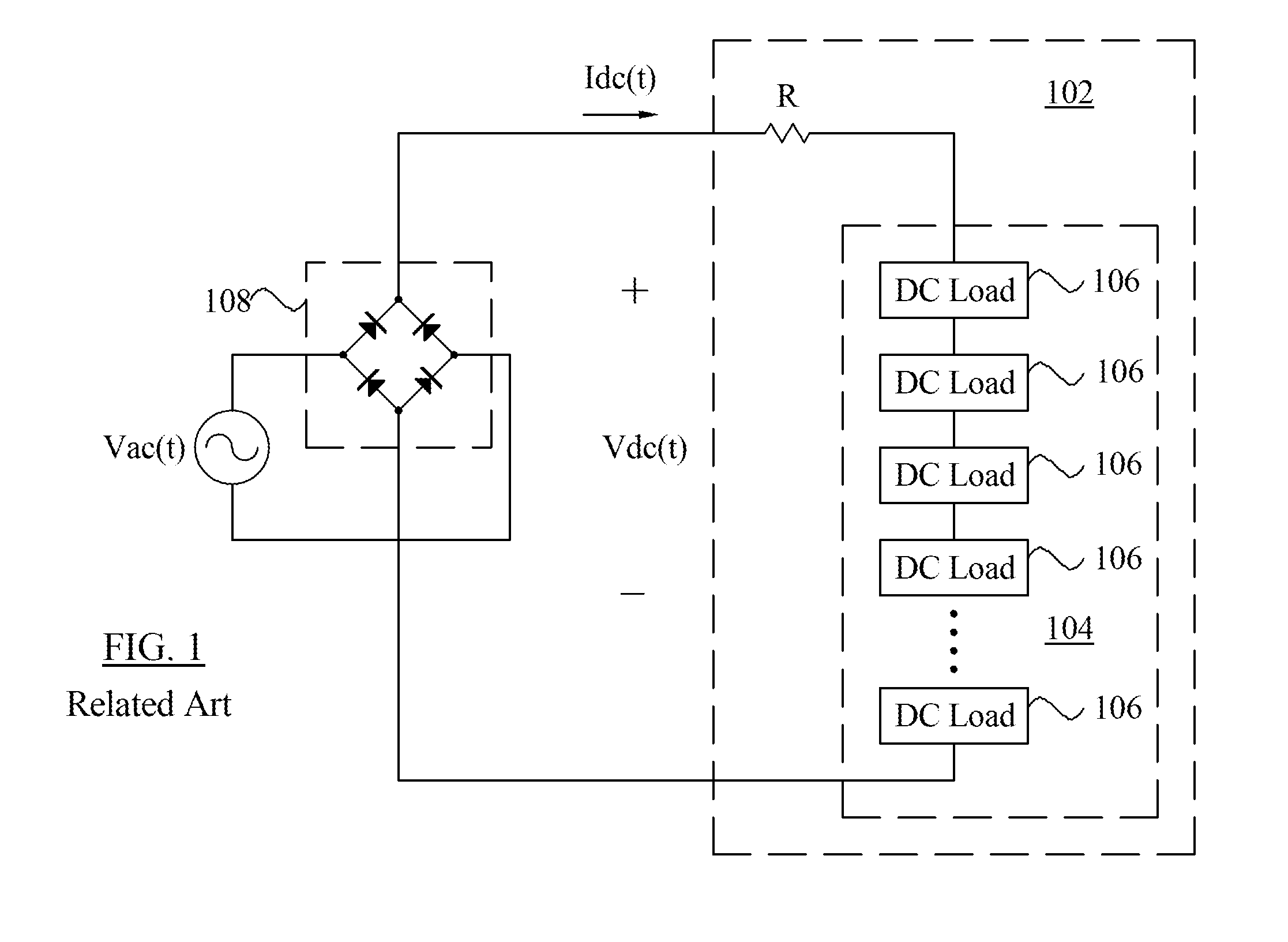
Misapplication of the magnitude of incoming AC line voltage Vac(t) and the DC load string 104 requirements can cause many problems, including shortened life of the individual DC loads 106, or insufficient operation of the DC load string 104.
Regrettably, the use of specifically designed DC loads 102 for a given incoming AC line voltage range results in manufacturing difficulties and restricted use of the DC load 102.
Accordingly, the required manufacture of DC loads 102 with specific or particular electrical characteristics to operate within a specifically commensurate magnitude of incoming AC line voltage Vac(t) becomes costly, and can lead to premature failure of the DC load 102 if misapplied by the consumer.
Additionally, with the proliferation of these light sources and the benefits of high volume production, they are becoming increasingly cost effective.
As illustrated in FIG. 2B, the application of voltage across an LED string generates an exponential increase in the current through it, which, if increased above a designed limit, Ion(max), may easily damage the LED string.
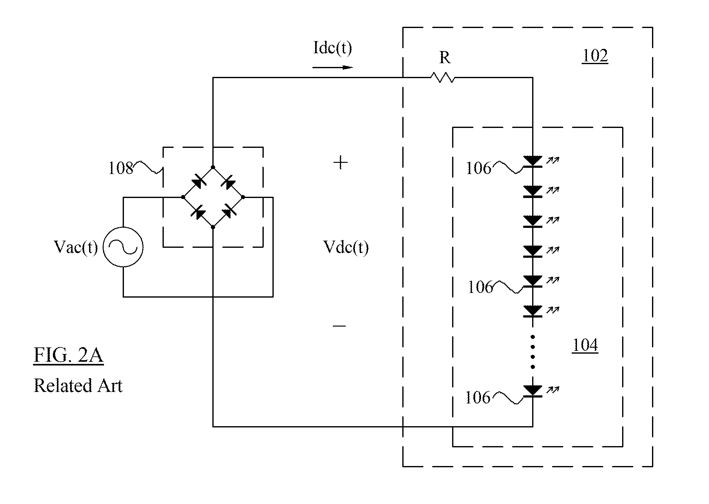
This benefit does not come without cost, as resistor R is dissipative, and therefore lowers the efficiency of the system, and may lead to thermal problems if the power dissipated is too large.
This results in poor power factor, as indicated by the pulse current waveform Idc(t) in FIG. 2D, where current flows only in the intervals between Ton to Toff, with high peak current Ipk 1.
The result of this pulsed current waveform is high peak current and poor power factor.
The penalties for low power

Method used


Image

  • Source and multiple loads regulator
  • Source and multiple loads regulator
  • Source and multiple loads regulator

Examples


Embodiment Construction

[0102]The detailed description set forth below in connection with the appended drawings is intended as a description of presently preferred exemplary embodiments of the invention and is not intended to represent the only forms in which the present invention may be constructed and or utilized.

[0103]The term “rectifier” in the context of this invention is generally used to describe a circuit that converts AC voltage at its input to DC voltage at its output. The term “DC voltage” is sometimes used to mean a stable, constant voltage, such as that from a battery, but is also used to describe a voltage of a single polarity, such as that appearing at the output (or DC) side of a bridge rectifier with a sinusoidal AC input voltage and a resistive load. In the present context, the DC voltage appearing at the output (or DC) side of the bridge rectifier is referred to as “rectified AC voltage.” The term “resistive” such as in “resistive load” in the context of this invention is generally used ...


PUM


Abstract

A circuit that has one or more control units that divide a load into two or more load groups, with each load group comprised of at least one load element. The one or more control units directing power from a power source to one or more of the load groups based on voltage variations in an output of the power source, load grouping, and operational parameters of the load elements. The circuit further includes one or more pass stages that regulate current flow from the power source to the load groups.

Description

CROSS-REFERENCE TO RELATED APPLICATIONS[0001]This Application claims the benefit of priority of co-pending U.S. Utility Provisional Patent Application No. 61 / 431,435, filed 11 Jan. 2011, the entire disclosure of which is expressly incorporated by reference in its entirety herein.BACKGROUND OF THE INVENTION[0002]1. Field of the Invention[0003]This invention is related to regulators and, more particularly, to a regulator circuit that can efficiently power a plurality of loads from a power source.[0004]2. Description of Related Art[0005]FIG. 1 depicts a conventional Alternating Current (or AC) driven Direct Current (or DC) load 102. As illustrated, a bridge rectifier 108 rectifies an incoming AC line voltage in a well-known manner with the resulting full-wave rectified AC voltage applied to the DC load 102, which is a series combination of individual DC loads 106 with substantially similar electrical characteristics in a DC load string 104 and current limiting resistor R. The current l...

Claims


Application Information

Patent Timeline
IPC IPC(8): H02M7/06
CPCH02J1/14H02J1/06H02J1/04H02M2001/0077H02M3/158H05B37/02H05B45/44H05B47/17H02M1/0077
Inventor LAZAR, JAMES FREDERICK
Owner BRAXTON ENG
Why Eureka
Try Eureka