
Live registration for vessel treatment

a technology for registering and treating vessels, applied in the field of accurate positioning for vessel intervention procedures, can solve the problems of complex mental merging operation, easy process error, and difficult positioning operation

Active Publication Date: 2012-07-12
KONINKLIJKE PHILIPS ELECTRONICS NV
View PDF2 Cites 24 Cited by
  • Summary
  • Abstract
  • Description
  • Claims
  • Application Information

AI Technical Summary

Benefits of technology

[0003]The present invention aims at providing the cardiologist or surgeon with better information during vessel interventions.
[0007]To base the registration on the detected calcification features provides the advantage that no additional feature, such as an intervention tool, has to be provided for the registration process. Further, the disadvantage of an interventional tool inside larger vessels, used for registration, leading to imprecise or false alignment due to the possible movement of the tool inside the vessel volume is thus prevented.
[0034]However, 3D data has the advantage that it can be used to derive the vessel representation, but is can also be used to help calcifications, vessel candidate selection, vessel candidate detection or vessel candidate tracking.

Problems solved by technology

This mental process is prone to error and makes positioning a delicate and tiring operation.
As an additional disadvantage, the breathing and heart beating motions make this mental merging operation more complex.

Method used


Image

  • Live registration for vessel treatment
  • Live registration for vessel treatment
  • Live registration for vessel treatment

Examples


Embodiment Construction

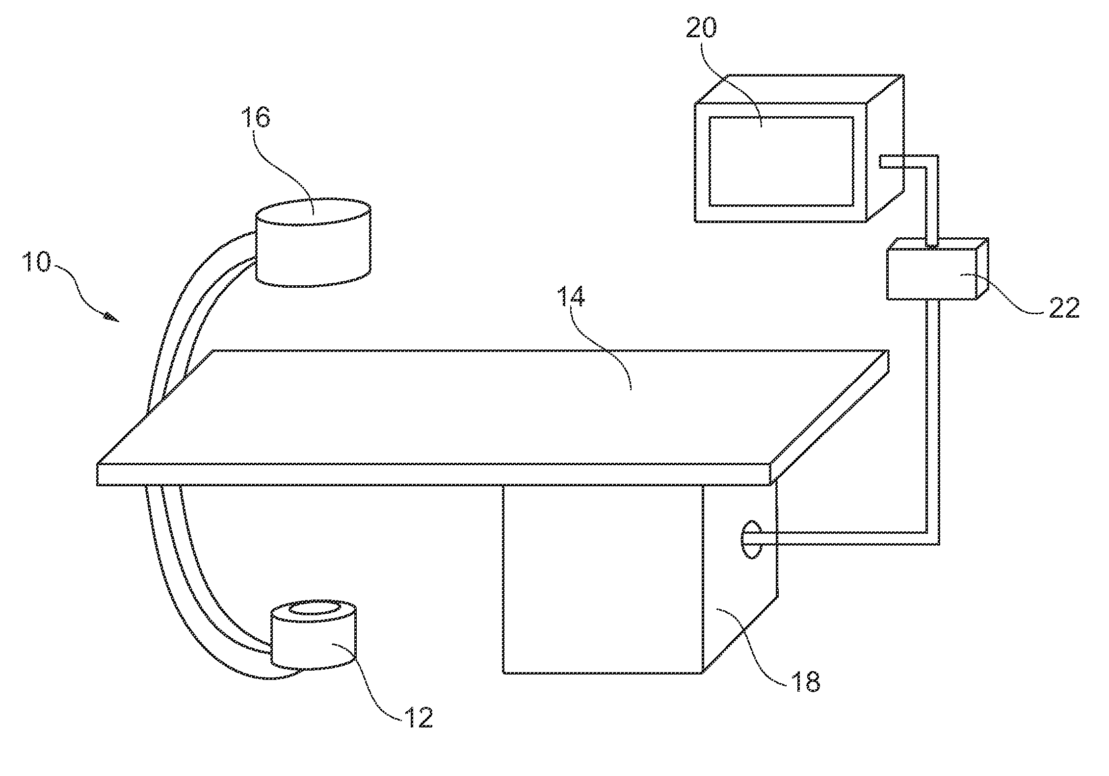
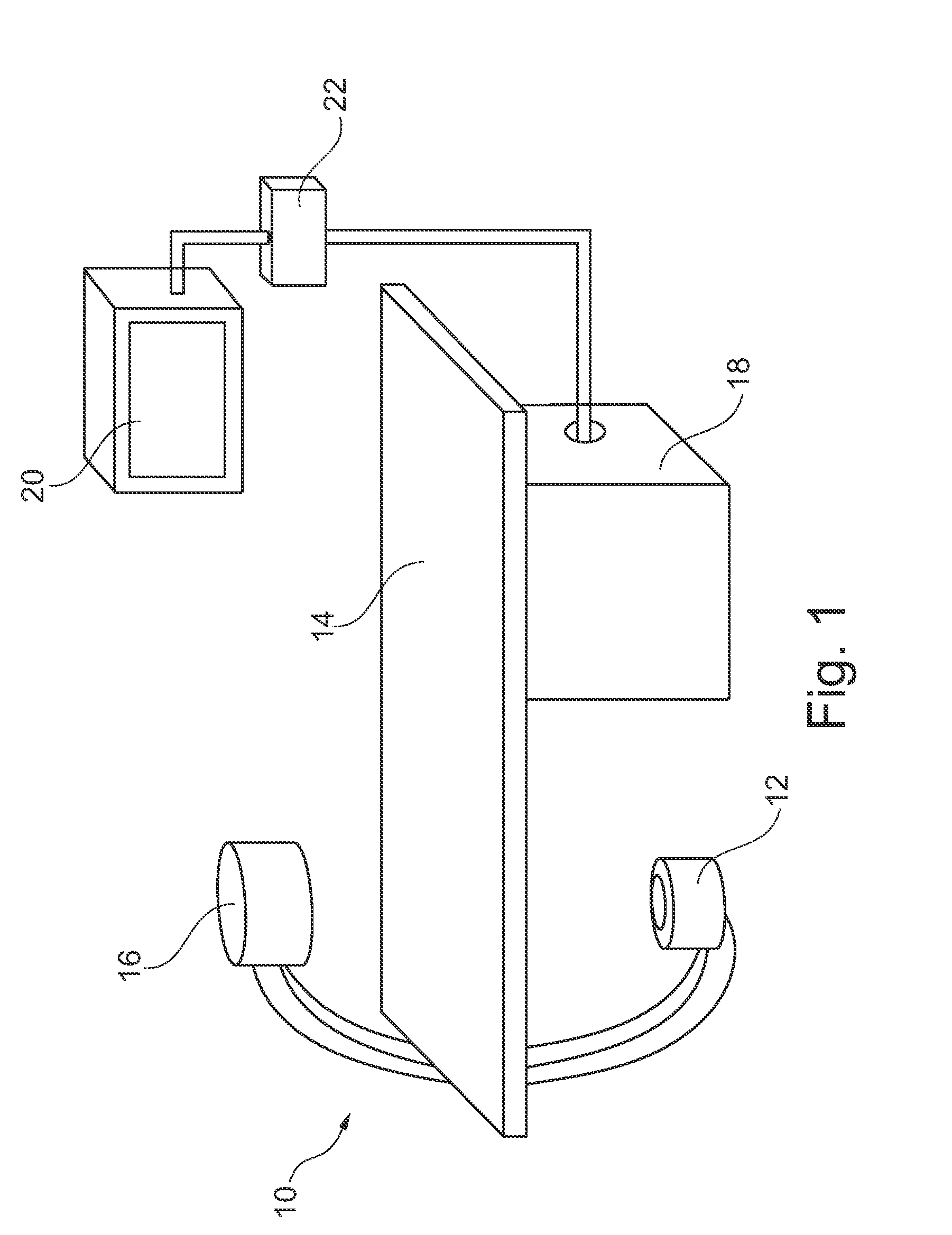
[0080]FIG. 1 schematically shows an X-ray imaging system 10 for the use in a catheterization laboratory with an examination apparatus for accurate positioning for heart valve replacement. The examination apparatus comprises an X-ray image acquisition device with a source of X-ray radiation 12 provided to generate X-ray radiation. A table 14 is provided to receive a subject to be examined. Further, an X-ray image detection module 16 is located opposite the source of X-ray radiation 12, i.e. during the radiation procedure the subject is located between the source of X-ray radiation 12 and the detection module 16. The latter is sending data to a data processing unit or calculation 18, which is connected to both the detection module 16 and the radiation source 12. The calculation unit 18 is located underneath the table 14 to save space within the catheterization laboratory. Of course, it could also be located at a different place, such as a different room. Furthermore a display device 2...


PUM


Abstract

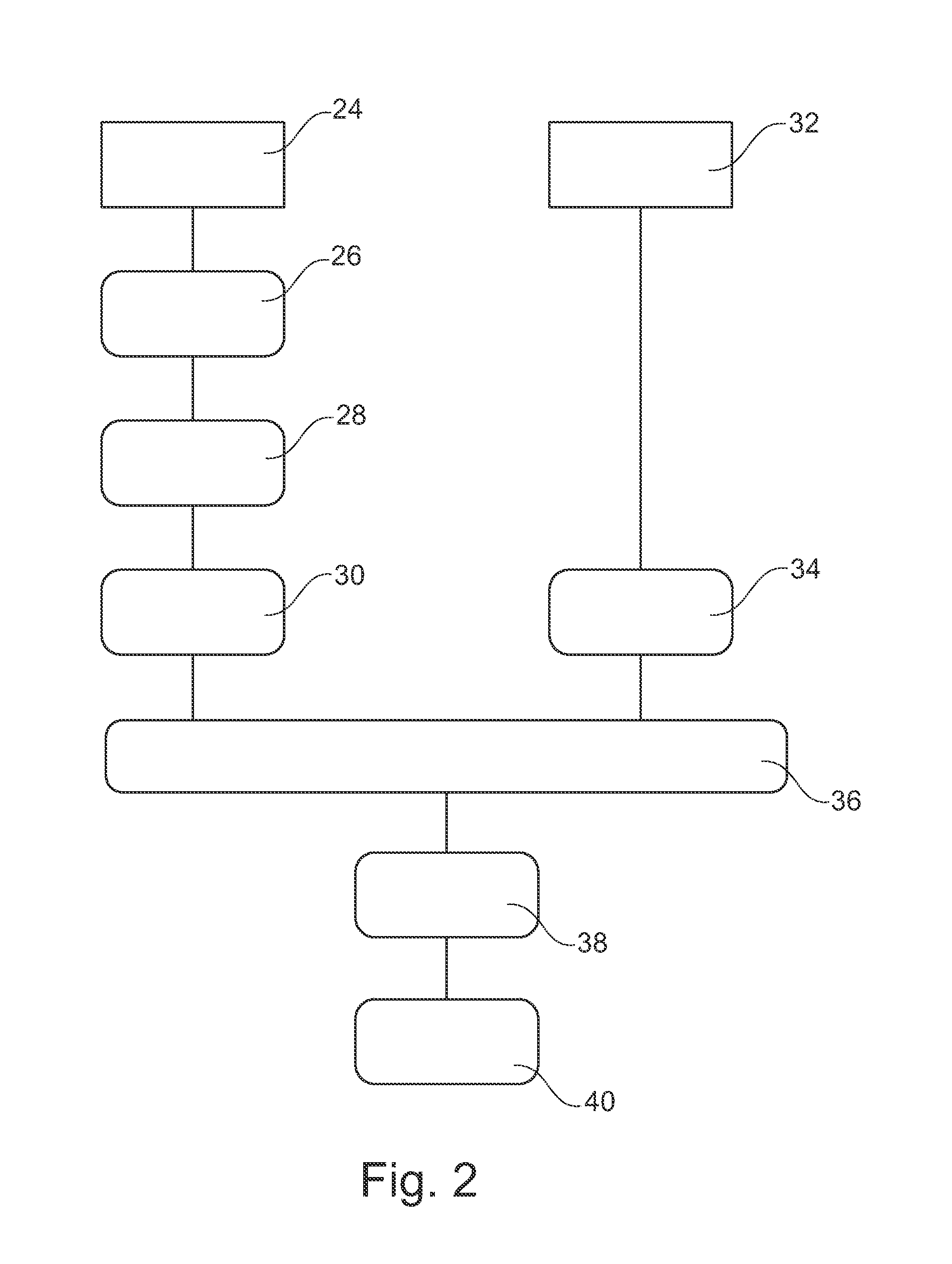
The present invention relates to accurate positioning for vessel intervention procedures, particularly to a method for accurate positioning for vessel intervention procedures, a medical imaging system for accurate positioning for vessel intervention procedures and a catheterization laboratory system for accurate positioning for vessel intervention procedures. First, at least one X-ray image of a vessel region of interest is acquired (24) with injected contrast agent. Further, vessel information data is identified (26) within the at least one acquired image. Then, first calcification features of the vessel in the vessel region of interest in the at least one acquired image are detected (28). Further, vessel representation is generated (30) using the vessel information data and the detected calcification features. Further, at least one current fluoroscopic image of the vessel region of interest is acquired (32). Then, second calcification features of the vessel in the vessel region of interest in the at least one current fluoroscopy image are detected (34), wherein the second calcification features are according to the first calcification features. Further, the vessel representation is registered (36) with the fluoroscopy image, wherein the calcification features are used for the registration. Then, a composite image is generated (38) by combining the vessel representation with the at least one fluoroscopy image. Further, a composite image is displayed (40).

Description

FIELD OF THE INVENTION[0001]The present invention relates to accurate positioning for vessel intervention procedures, particularly to a method for accurate positioning for vessel intervention procedures, a medical imaging system for accurate positioning for vessel intervention procedures and a catheterization laboratory system for accurate positioning for vessel intervention procedures.BACKGROUND OF THE INVENTION[0002]Vessel intervention procedures often comprise the task to position a device inside the vessel prior to further steps. For example, stents may have to be positioned inside the vessel prior to deployment. As another example, in percutaneous aortic valve replacement interventions (PAV replacement), the implantable device, in other words an artificial heart valve replacement, is positioned, for example, under fluoroscopy prior to deployment. In the PAV, to achieve this positioning, a super aortic angiography with contrast agent is performed in order to determine the optima...

Claims


Application Information

Patent Timeline
Patent Type & Authority Applications(United States)
IPC IPC(8): G06K9/00
CPCA61B5/02007A61B6/12A61B6/4441A61B6/463A61B6/466A61B6/481G06T2207/30101A61B6/5247A61B19/52A61B2019/5238A61B2019/5289G06T7/0028G06T2207/10121A61B6/504A61B90/36A61B2090/364A61B2090/376G06T7/33
Inventor FLORENT, RAOULBAKKER, NICOLAAS HYLKE
Owner KONINKLIJKE PHILIPS ELECTRONICS NV
Learn More