Gas concentration arrangement

a technology of gas concentration and arrangement, which is applied in the direction of separation process, membrane, servomotor, etc., can solve the problems of high noise, high noise, and high noise of traditional oxygen concentrators, and achieve the effect of low noise and easy maintenan

Inactive Publication Date: 2012-07-12
KONINKLIJKE PHILIPS ELECTRONICS NV
View PDF9 Cites 17 Cited by
  • Summary
  • Abstract
  • Description
  • Claims
  • Application Information

AI Technical Summary

Benefits of technology

[0005]It is an object of the invention to provide a gas concentration arrangement, a gas concentration system and a gas pump, which are cost-saving, can be operated at low noise and are easy to maintain.

Problems solved by technology

Traditional Oxygen concentrators are bulky, heavy, and require ongoing maintenance by patients and homecare providers.
Due to the compressor unit, such devices produce noise and heat.

Method used


Image

  • Gas concentration arrangement
  • Gas concentration arrangement
  • Gas concentration arrangement

Examples


first embodiment

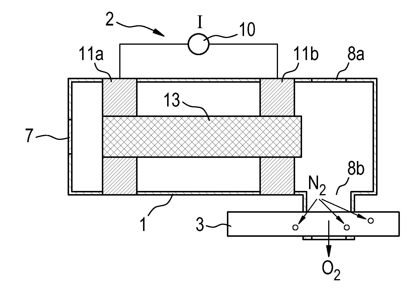
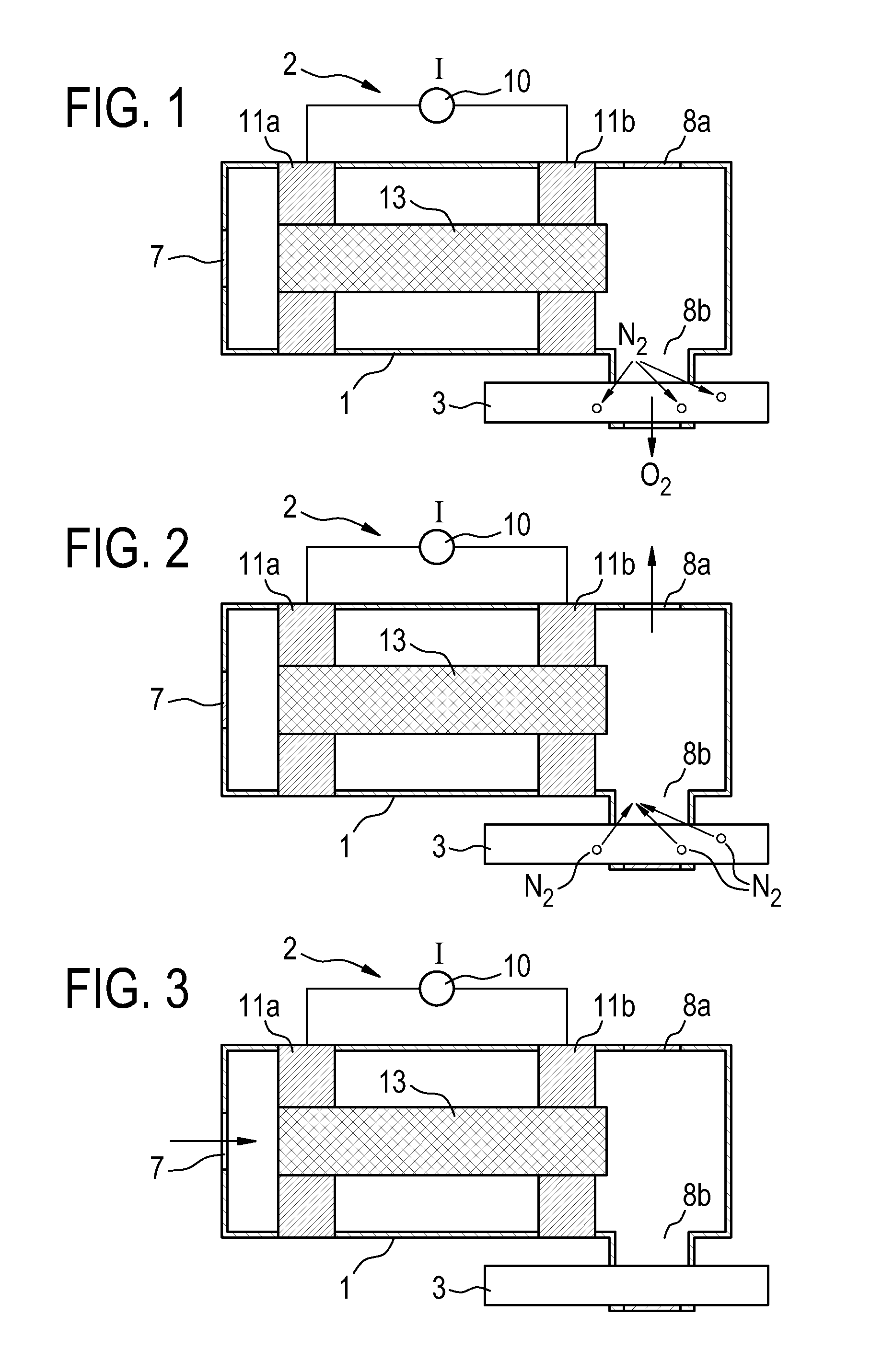
[0037]The gas concentration arrangement comprises a discharge chamber 1 including an input side and an output side, a gas discharge device 2 for generating a gas discharge inside the discharge chamber 1 for generating a pressure gradient on the output side of the discharge chamber 1, and a gas selection device 3, which is arranged on the output side of the chamber 1 and which is exposable to a gas flow generated by the pressure gradient. The “input side” of the discharge chamber 1 is the side of the discharge chamber 1 from which gas flows into the chamber 1, the “output side” of the discharge chamber 1 is the side of the discharge chamber 1, where gas flows out of the discharge chamber 1.

[0038]The gas discharge device comprises a coupling device to generate a gas discharge by capacitive, inductive, surface wave and / or microwave coupling, and an energy source 10 to provide the coupling device with an alternating current. In this embodiment, the coupling device comprises two electro...

second embodiment

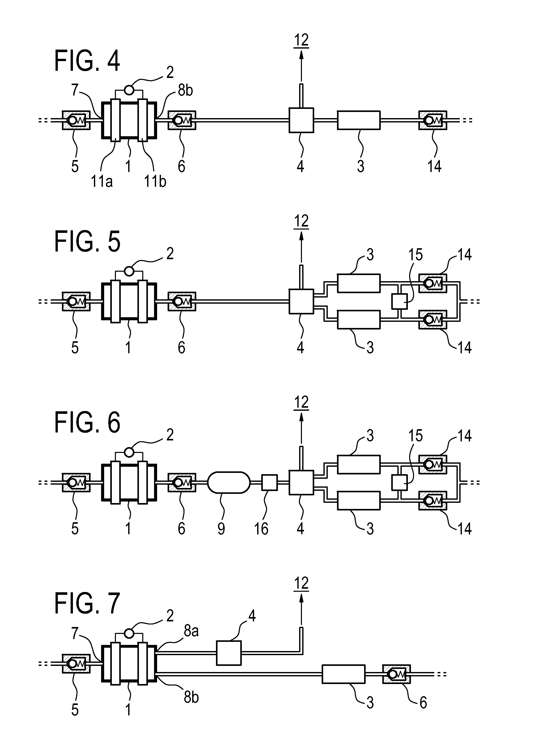
[0048]FIG. 4 displays a gas concentration arrangement.

[0049]The gas concentration arrangement according to the second embodiment comprises an inlet valve 5, a gas discharge chamber 1, a gas discharge device 2, an outlet valve 6, a gas exhaust device 4, a gas selection device 3 and a third valve 14, which are connected to each other in the order as stated. The third valve 14 is, for example, a two-way valve or, preferably, a non-return valve.

[0050]In this embodiment, the discharge chamber 1 is a glass sphere, for example a hard glass, with an inner diameter of 4 cm, the electrodes 11a, 11b of the discharge device 2 are inner carbon rod electrodes, for example with an electrode diameter of 4 mm and an electrode distance of 1 has two glass pipes (not shown) as gas inlet 7 and as gas outlet 8a. In contrast to the first embodiment, a second gas outlet 8a is not provided. At the gas inlet 7 and at the outlet 8b non-return valves 5, 6 are mounted. Due to these non-return valves 5, 6, gas c...

third embodiment

[0057]FIG. 5 displays a gas concentration arrangement.

[0058]In addition to the second embodiment, the third embodiment comprises a second gas selection device 3, a further third valve 14 and a fourth valve 15, wherein the second gas selection device 3 and the further third valve 14 are connected to the exhaust gas device 4 parallel to the first gas selection device 3 and valve 14. Between the gas selection devices 3 and the third valves 14, the fourth valve 15 is connected parallel to these two lines. After the third valves 14, both lines are joined. Alternatively, fourth valve 15 could be substituted by an orifice.

[0059]The arrangement can be operated in the following manner.

[0060]In a first step, fresh air is pumped by modulated gas discharge inside the chamber 1 from the surroundings or an reservoir through the inlet valve 5, the discharge chamber 1, the outlet valve 6 and the gas exhaust device 4 to one of the two gas selection devices 3, leading to a flow of oxygen enriched air...


PUM


Abstract

The invention relates to the field of increasing the amount of a gas component in a gas mixture, especially of enriching air with oxygen. According to the invention, the gas concentration arrangement comprises: a discharge chamber (1) including an input side and an output side, —a gas discharge device (2) for generating a gas discharge inside the discharge chamber (1) for generating a pressure gradient on the output side and/or the input side of the discharge chamber (1), and a gas selection device (3), which is arranged on the input side or the output side of the chamber (1) and which is exposable to a gas flow generated by the pressure gradient.

Description

FIELD OF THE INVENTION[0001]The invention relates to the field of increasing the amount of a gas component in a gas mixture, especially of enriching air with oxygen.BACKGROUND OF THE INVENTION[0002]Oxygen therapy is the administration of Oxygen as a therapeutic modality. Oxygen therapy benefits the patient by increasing the supply of Oxygen to the lungs and thereby increasing the availability of Oxygen to the body tissues. The main homecare application of Oxygen therapy is for patients with severe chronic obstructive pulmonary disease (COPD), a disease that affects more than 13 million patients in the US.[0003]For on-demand generation of Oxygen, commercial solutions, so-called Oxygen concentrators, have been developed in the past. WO98 / 56488 discloses an oxygen concentrator, which has a first molecular sieve bed connected to a four-way valve, which either joins the sieve bed to a pressurized air source or alternatively vents it to atmosphere. A second molecular sieve bed is also joi...

Claims


Application Information

Patent Timeline
Patent Type & Authority Applications(United States)
IPC IPC(8): B01J7/00F04B41/00
CPCB01D53/0438B01D53/22B01D63/00B01D2256/12B01D2313/18B01D2259/40098B01D2259/4541B01D2259/818B01D2257/102
Inventor HILBIG, RAINER
Owner KONINKLIJKE PHILIPS ELECTRONICS NV
Why Eureka
Try Eureka