Endoscope diagnosis system

a diagnosis system and endoscope technology, applied in the field of endoscope diagnosis system, can solve the problems of not being able to distinguish between a high blood level region and a low blood level region easily, and merely displaying the information on the hemoglobin index ihb in pseudo-color, so as to achieve high contrast and improve the diagnosis of a region

Inactive Publication Date: 2012-07-12
FUJIFILM CORP
View PDF1 Cites 19 Cited by
  • Summary
  • Abstract
  • Description
  • Claims
  • Application Information

AI Technical Summary

Benefits of technology

[0020]According to the present invention, the blood vessels in the superficial layer can be placed in high contrast by enhancing the blue image signal B of the narrowband light image. Further, the blood level in the medium to deep layer of a mucous membrane can be represented in gradation of red in an image by enhancing the red according to the value of hemoglobin index. Thus, simultaneously displaying the information on a mucous membrane medium-to-deep layer blood amount distribution and enhanced superficial-layer blood vessels in endoscopic observation compensates for a disadvantage of the narrowband light observation that discovery of a site of lesion or determination of the range of an affected region is difficult with a mere inspection into the superficial layer of a mucous membrane and enables improved diagnosis of a region affected by a tumor including the undifferentiated type.

Problems solved by technology

According to JP 3559755 B, however, while the blue-light image acquired by illuminating the subject with the narrowband light of blue light contains information on superficial-layer blood vessels, merely displaying the blue-light image as it is did not permit easy observation of superficial-layer blood vessels.
Further, while the hemoglobin index IHb contains information on the blood level in the medium to deep layer, merely displaying the information on the hemoglobin index IHb in pseudo color did not permit easy distinction between a high blood level region and a low blood level region.

Method used


Image

  • Endoscope diagnosis system
  • Endoscope diagnosis system
  • Endoscope diagnosis system

Examples


first embodiment

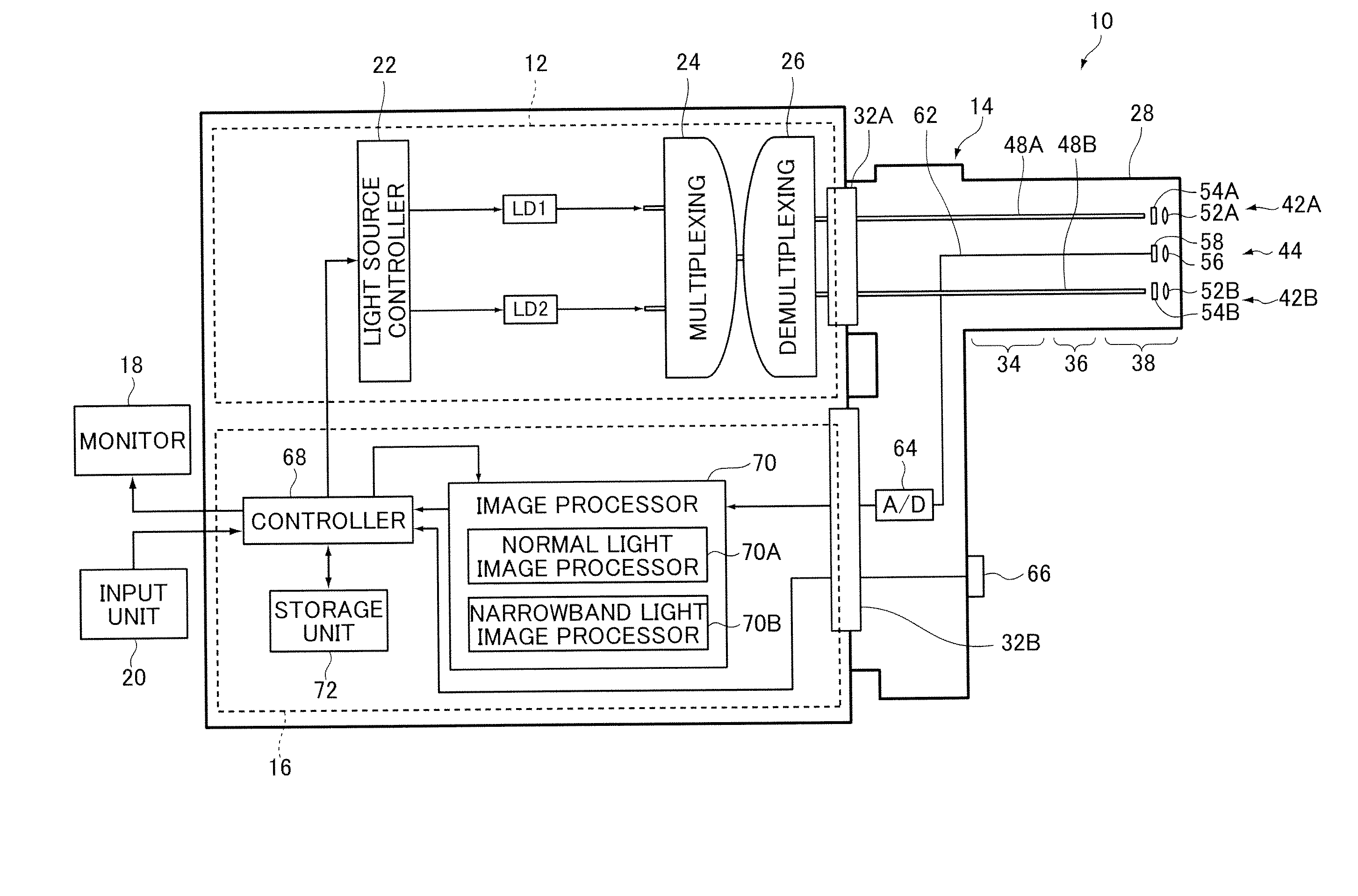
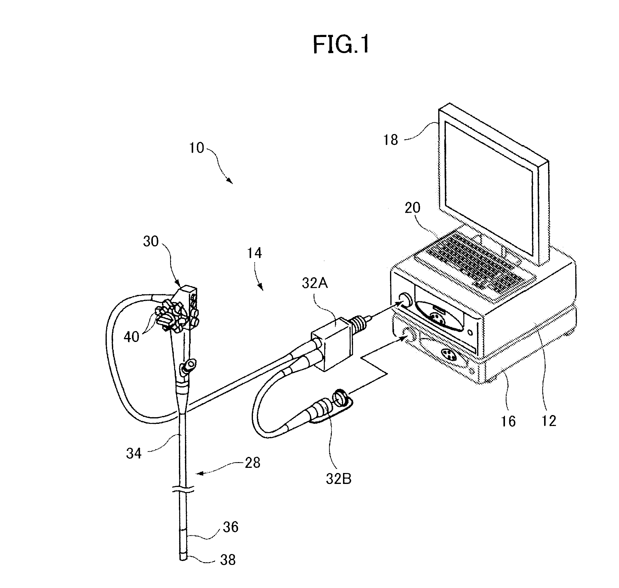
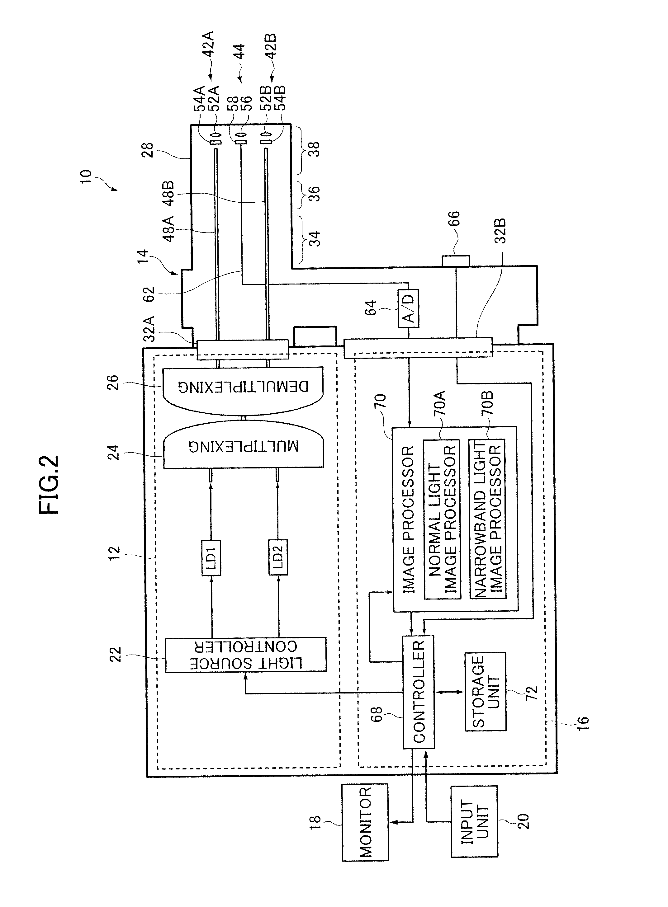
[0029]FIG. 1 is an external view of a first embodiment representing a configuration of the endoscopic diagnosis system according to the invention; FIG. 2 is a block diagram representing an internal configuration thereof. A endoscopic diagnosis system 10 illustrated in these figures comprises a light source device 12 for generating light having a given range of wavelength; an endoscope device 14 for guiding light emitted from the light source device 12 to illuminate a subject's region under observation with the illumination light and imaging the reflected light from the subject; a processor 16 for image-processing the image acquired by the endoscope device 14 and outputting an endoscopic image; a monitor 18 for displaying the endoscopic image outputted from the processor 16; and an input unit 20 for receiving input operations.

[0030]The endoscopic diagnosis system 10 is capable of normal light (white light) observation mode for illuminating the subject with normal light (white light) ...

second embodiment

[0086]Next, a second embodiment will be described.

[0087]FIG. 7 is a block diagram of the second embodiment illustrating an internal configuration of the endoscopic diagnosis system shown in FIG. 1. The light source device 12 of the endoscopic diagnosis system illustrated in that drawing comprises a white light source 84, a narrowband filter 86, a rotation controller 88, a lens 90, and the coupler 26.

[0088]The white light source 84 may, for example, be in operation and emits white light whenever the light source device 12 is in operation. Examples of the white light source 84 include white light emitting lamps such as a xenon lamp, a fluorescent lamp, and a mercury lamp as well as any other light source that emits white light.

[0089]The narrowband filter 86 is a band pass filter that filters the white light emitted from the white light source 84 to pass light having a given wavelength range. The narrowband filter 86 has the shape of a disk and comprises a first to a third light filter...


PUM


Abstract

An endoscopic diagnosis system includes a white light source, a narrowband light source for emitting narrowband light having a given wavelength range of blue light, an image sensor receiving reflected light of white light and the narrowband light emitted with a given emission ratio to illuminate a subject from the subject to acquire a narrowband light image, and an image processor for calculating an enhanced luminance signal where a blue image signal of the narrowband light image is enhanced, calculating a hemoglobin index representing blood level in a medium to deep layer of a mucous membrane from a green image signal and a red image signal of the narrowband light image, calculating an enhanced color difference signal enhancing red according to a value of the hemoglobin index, and producing an image signal of an endoscopic image for display.

Description

BACKGROUND OF THE INVENTION[0001]The present invention relates to an endoscopic diagnosis system for simultaneously observing the blood level (amount of blood) in the medium to deep layer of a mucous membrane and blood vessels in the superficial layer.[0002]There is conventionally used an endoscope device wherein white light (normal light) emitted from a light source device is guided to the tip of an endoscope to illuminate a region under observation of a subject, and the reflected light is imaged to acquire a normal light image (white light image) in order to perform normal light observation (white light observation). In recent years, there is used an endoscope device wherein a region of a subject under observation is illuminated by narrowband light (special light) having a given wavelength range, and the reflected light thereof, for example, is imaged to acquire a special light image (narrowband light image) in order to perform special light observation in addition to normal light...

Claims


Application Information

Patent Timeline
Patent Type & Authority Applications(United States)
IPC IPC(8): A61B6/00
CPCA61B1/00009A61B1/043A61B1/063A61B5/14551A61B1/0646A61B1/0653A61B1/0638A61B1/000094A61B1/0655
Inventor SAITO, TAKAAKI
Owner FUJIFILM CORP
Why Eureka
Try Eureka