Hydraulically Activated Tension Relief System for Threaded Fasteners

a technology of tension relief system and threaded fastener, which is applied in the direction of power driven tools, metal-working hand tools, metal-working apparatus, etc., can solve the problems of prone or vulnerable to galling, damage or seizing of threaded features, and damage or seizing of said components, so as to prevent galling of threaded features and reduce load

Inactive Publication Date: 2012-07-19
INTEGRA SERVICES TECH
View PDF1 Cites 12 Cited by
  • Summary
  • Abstract
  • Description
  • Claims
  • Application Information

AI Technical Summary

Benefits of technology

[0008]Accordingly, an object of this invention is the prevention of galling threaded features during...

Problems solved by technology

A common complication that arises when fastening or disassembling threaded components is galling which can result in damage to the threaded features or seizing of said components.
Such damage or seizing can often be costly to repair or remedy.
The fastening of threaded components in which interlocking threaded features are slid past each other under high loads is an industrial operation which is notably prone or vulnerable to galling.
It is these local values which can result in elevated friction, promote material transfer, and induce phase transition.
Furthermore, galling is especially likely when disassembling threaded fasteners which have been in service for several years due to additional debris from local oxidation, foreign contaminants, and the breakdown, seepage, and removal of assembly lubricants.
As a result, said protrusion could cause damage to the ductile bulk material on which the oxide layer originally formed, thus creating a region of plastic flow around said protrusion.
Thus, the high loads an...

Method used


Image

  • Hydraulically Activated Tension Relief System for Threaded Fasteners
  • Hydraulically Activated Tension Relief System for Threaded Fasteners
  • Hydraulically Activated Tension Relief System for Threaded Fasteners

Examples


Embodiment Construction

[0034]With reference to the annexed figures, the preferred embodiments of the present invention will be herein described for indicative purposes and by no means represent limitations.

[0035]The figures and description attached to it are only intended to illustrate the idea of the invention. As to the details, the invention may vary within the scope of the claims. So, the size and shape of the tension relief system may be chosen to best fit the fastened assembly.

[0036]Also, as used hereinabove and hereinafter, the term “stud” generally refers to stud, bolt, rod and other similarly shaped fasteners used in securing assemblies.

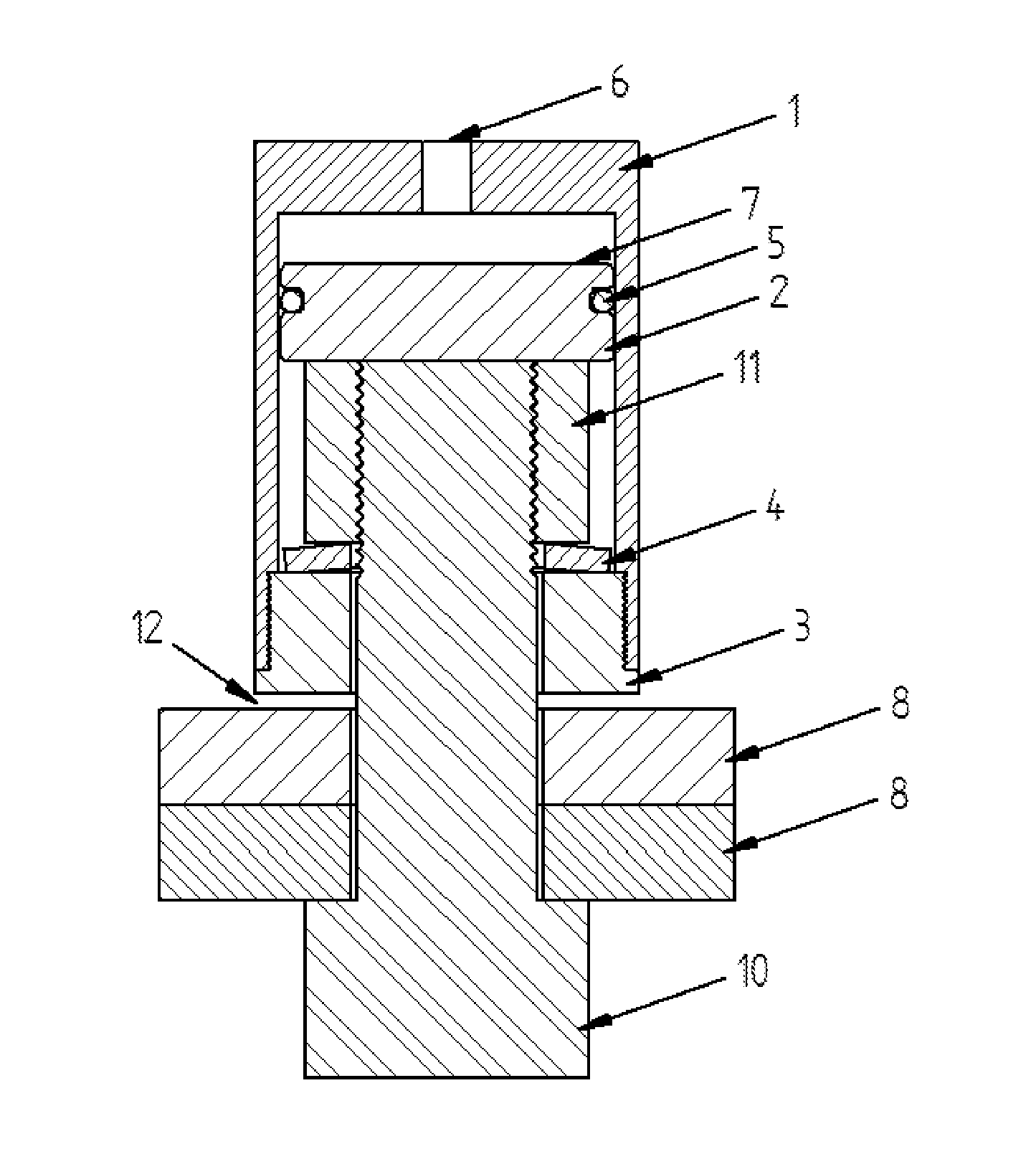
[0037]In accordance with the present invention, there is provided a tension relief system for threaded fasteners (FIGS. 1 to 15) comprising an outer body (1), an inner piston (2), a pressure area (7) defined between the outer body and inner piston, sealing means (5) located between the outer body and inner piston in an annular groove, a compression disk spring (4)...


PUM

PropertyMeasurementUnit
Pressureaaaaaaaaaa
Tensionaaaaaaaaaa

Abstract

A tension relief system for threaded fasteners comprises a main body housing a piston for generating a clamping load, seals to maintain the hydraulic pressure within the pressure chamber, an external pressure port extending through the body to the pressure chamber and adapted to be connected to an external pressure source, a connector on which the main body may be mounted, and a spring which may be compressed through the relative motion of the piston and the connector.

Description

FIELD OF THE INVENTION[0001]The present invention relates to a hydraulically activated tension relief system for threaded fasteners. More specifically, the present invention relates to the use of a hydraulic ram to eliminate the tensile load in a bolt.BACKGROUND OF THE INVENTION[0002]A common complication that arises when fastening or disassembling threaded components is galling which can result in damage to the threaded features or seizing of said components. Such damage or seizing can often be costly to repair or remedy. Galling is a form of adhesive wear and material transfer between metallic surfaces during operations in which relative motion of said surfaces is involved. The fastening of threaded components in which interlocking threaded features are slid past each other under high loads is an industrial operation which is notably prone or vulnerable to galling. Galling is a major concern in said application because the same features which promote galling, such as material duct...

Claims


Application Information

Patent Timeline
IPC IPC(8): B23P19/06
CPCB23P19/06B23P19/067Y10T29/5383B25B29/02B25B21/002
Inventor PSIMAS, MICHAEL JAMES
Owner INTEGRA SERVICES TECH
Why Eureka
Try Eureka