Method of desulfurizing steel

a desulfurizing steel and desulfurizing technology, applied in the direction of manufacturing tools, lighting and heating equipment, furnaces, etc., can solve the problems of high adverse effect on the productivity of the furnace, and excessive refractory wear on the furnace walls, so as to reduce the carbon level

Active Publication Date: 2012-07-19
NUCOR CORP
View PDF4 Cites 7 Cited by
  • Summary
  • Abstract
  • Description
  • Claims
  • Application Information

AI Technical Summary

Benefits of technology

[0002]Certain commercial steel compositions require relatively low amounts of carbon (less than 0.05%), nitrogen (less than 50 ppm), and sulfur (less than 30 ppm). In the past, methods of producing these low carbon and low sulfur steels used a combination of processes in a steelmaking furnace and a degasser. The prior method involved reducing the carbon levels in the steel composition in the steelmaking furnace, such as an electric arc furnace (EAF), making alloy additions during the tapping process to desulfurize and alloy the steel, and then shipping the steel to the degasser such as a vacuum tank degasser (VTD). This processing route was simple and quite straightforward.

Problems solved by technology

The prior process had drawbacks, including high refractory wear on the steelmaking furnace.
The elevated tapping temperatures and high oxygen content required before tapping the steelmaking furnace had an adverse effect on productivity at the furnaces.
The high temperatures and high oxygen conditions enabled high amounts of FeO in the slag at the high temperatures, causing excessive refractory wear on the furnace walls.
Also the high FeO content in the slag results in lower efficiency in steelmaking as more iron units are lost in the slag.
Recently, the price of low carbon ferro-alloys has increased significantly, making this method economically undesirable to produce such low carbon steel.
Further, lowering the amount of carbon in the steel composition in the steelmaking furnace required additional decarburization time, which also adversely affected productivity at the steelmaking furnace.
In certain applications, aluminum is not desired in the steel product, requiring additional compositions and processes to retain the aluminum in the slag.

Method used


Image

  • Method of desulfurizing steel
  • Method of desulfurizing steel
  • Method of desulfurizing steel

Examples


Embodiment Construction

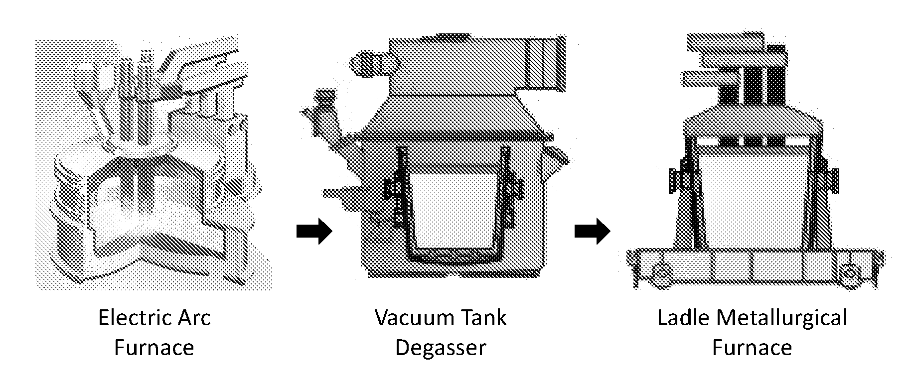
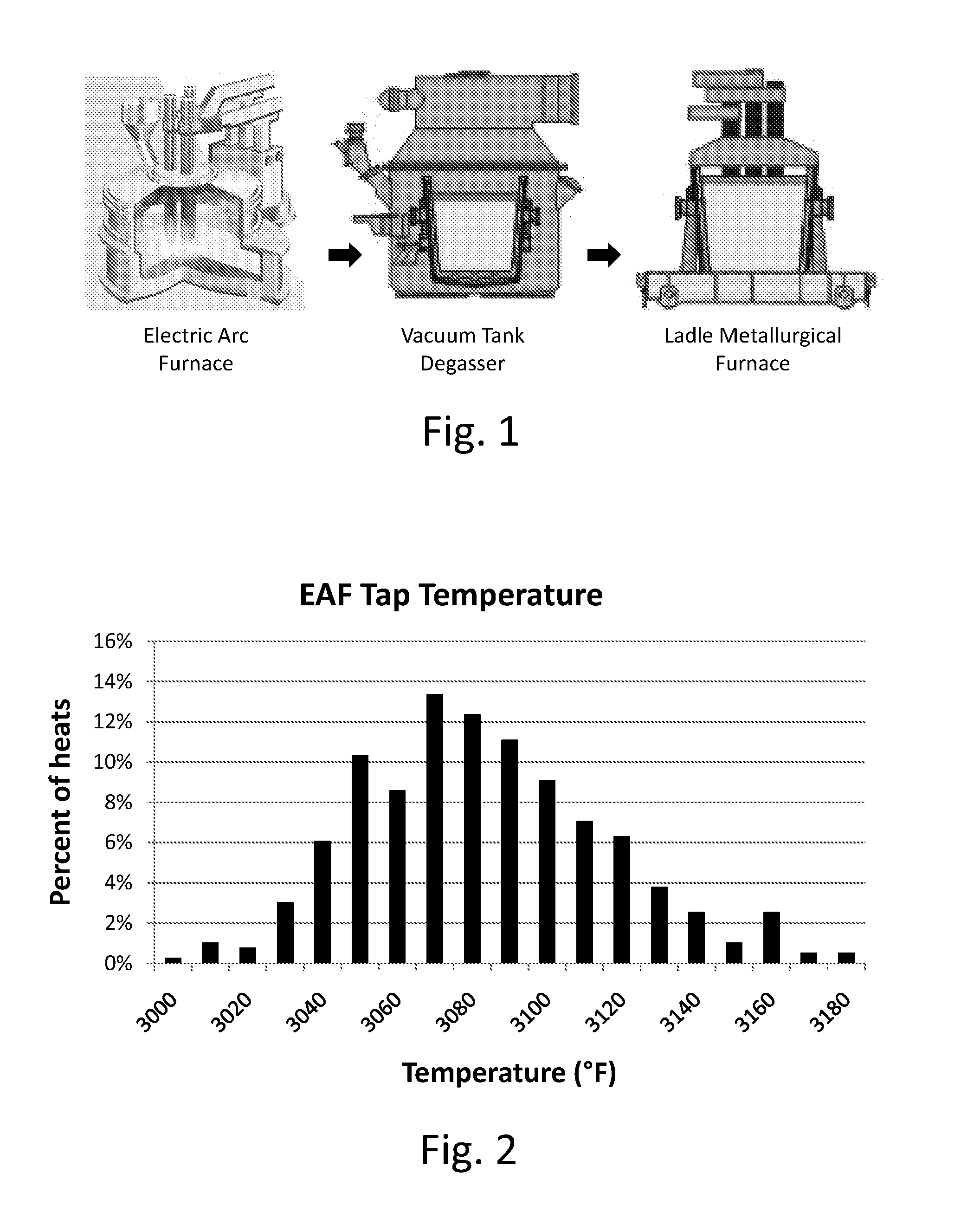
[0072]In a process for preparing steel for casting, as shown diagrammatically in FIG. 1, the steel typically progresses from an electric arc furnace (EAF) to a vacuum tank degasser (VTD) to a ladle metallurgical furnace (LMF) before casting. The steel grades produced by the presently disclosed method typically have carbon less than about 0.05% by weight. The steel grade also typically has low nitrogen less than about 0.005% by weight and low sulfur less than about 0.003% by weight, or less than about 0.0015% by weight.

[0073]A steel melt shop typically has one or more electric arc furnaces, such as a 120 ton (metric ton) EAF equipped with 110 megavolt-ampere (MVA) transformers. Such electric arc furnaces may be between about 30 ton and 400 ton capacity, but are generally for continuous casting between 60 and 120 tons capacity. Each furnace may contain gas injection lances, such as a More brand gas injector system, through which a combination of oxygen and natural gas can be blown int...


PUM

PropertyMeasurementUnit
temperatureaaaaaaaaaa
tap temperatureaaaaaaaaaa

Abstract

A method of desulfurizing steel including steps of forming a slag over a molten metal, drawing a vacuum to less than 5 torr over the slag and molten metal, stirring the molten metal and slag, and deoxidizing and desulfurizing the molten metal and slag to degas the steel reducing at least sulfur, nitrogen, oxygen, and hydrogen contents, and reducing activity of oxygen in the molten metal to less than 30 ppm. The method includes forming a slag composition after degassing the steel comprising CaO between about 50 and 70% by weight, SiO2 between about 20 and 28% by weight, CaF2 between about 5 and 15% by weight, MgO not more than 8% by weight, Al2O3 not more than 1% by weight, and a combination of FeO+MnO not more than 2% by weight, where the sum of CaO+CaF2+SiO2+MgO is at least 85% by weight.

Description

[0001]This application claims priority to U.S. patent application Ser. No. 13 / 007,163 filed Jan. 14, 2011, the disclosure of which is incorporated herein by reference.BACKGROUND AND SUMMARY[0002]Certain commercial steel compositions require relatively low amounts of carbon (less than 0.05%), nitrogen (less than 50 ppm), and sulfur (less than 30 ppm). In the past, methods of producing these low carbon and low sulfur steels used a combination of processes in a steelmaking furnace and a degasser. The prior method involved reducing the carbon levels in the steel composition in the steelmaking furnace, such as an electric arc furnace (EAF), making alloy additions during the tapping process to desulfurize and alloy the steel, and then shipping the steel to the degasser such as a vacuum tank degasser (VTD). This processing route was simple and quite straightforward.[0003]To achieve the steel composition requirements of such commercial grades in the past, steel with very low carbon levels, ...

Claims


Application Information

Patent Timeline
Patent Type & Authority Applications(United States)
IPC IPC(8): C21C1/02
CPCC21C7/06C21C7/0645C21C2300/08C21C7/10C21C7/076C21C5/54Y02P10/20C21C7/00
Inventor PANDA, DHIRENROSS, NEALMCQUILLIS, GARYJENKINS, JEROME
Owner NUCOR CORP
Why Eureka
Try Eureka