Reformate cooling system and method for use in a fuel processing subsystem

a cooling system and fuel processing technology, applied in the direction of combustible gas production, electrochemical generators, lighting and heating apparatus, etc., can solve the problems of relatively complicated coolant control and the typical effectiveness of heat exchangers, and achieve the effect of reducing the level of carbon monoxid

Inactive Publication Date: 2007-03-20
MODINE MFG CO
View PDF2 Cites 2 Cited by
  • Summary
  • Abstract
  • Description
  • Claims
  • Application Information

AI Technical Summary

Benefits of technology

[0005]In accordance with one form of the invention, a reformate cooling system is provided for use with a fuel processing subsystem for reducing a level of carbon monoxide in a reformate flow for a proton exchange membrane fuel cell system. The fuel processing subsystem includes first and second preferential oxidizers to oxidize the carbon monoxide carried in the reformate flow. The second preferential oxidizer is located downstream from the first preferential oxidizer with respect to the reformate flow and requires a lower catalytic reaction temperature range for the reformate flow than the first preferential oxidizer. The reformate cooling system includes first and second heat exchanger units to transfer heat from the reformate flow to a coolant flow. The first heat exchanger unit includes first and second core portions through which the reformate flow and a coolant flow pass in heat exchange relation to each other. The first heat exchanger unit is located upstream from the first preferential oxidizer with respect to the reformate flow. The second heat exchanger unit includes third and fourth core portions through which the reformate flow and the coolant flow pass in heat exchange relation. The second heat exchanger unit is located upstream from the second preferential oxidizer and downstream from the first preferential oxidizer with respect to the reformate flow.

Problems solved by technology

However, the use of liquid-cooled heat exchangers for the above purpose presents a challenge in successfully maintaining the required temperatures during turndown (reduced power) operation of the fuel cell system wherein the flow rate of the reformate flow is reduced from that required for full power operating conditions.
Specifically, because the heat exchangers need to be designed for the appropriate heat transfer effectiveness at full flow rate, the heat exchangers will typically be too effective when the flow rate of the reformate flow is reduced.
However, this is complicated by the distribution of the CO cleanup into several different reactions, each of which requires a heat exchanger to control the temperature of the reformate flow.
Because the heat exchangers will typically not all have the same response to the above described adjustments at turndown, the coolant flow and / or temperature to each heat exchanger may have to be separately controlled, resulting in a relatively complicated coolant control scheme with duplicate by-pass valves, recirculation pumps, etc.

Method used


Image

  • Reformate cooling system and method for use in a fuel processing subsystem
  • Reformate cooling system and method for use in a fuel processing subsystem
  • Reformate cooling system and method for use in a fuel processing subsystem

Examples


Embodiment Construction

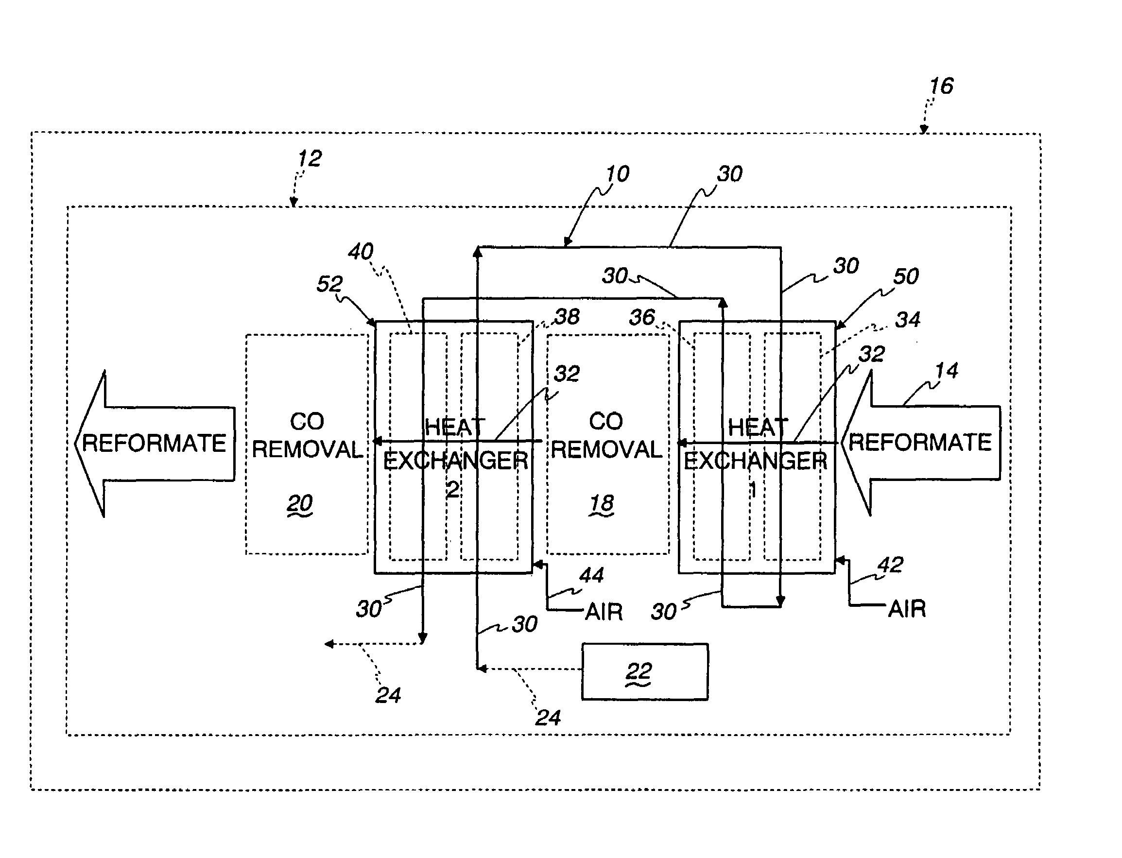
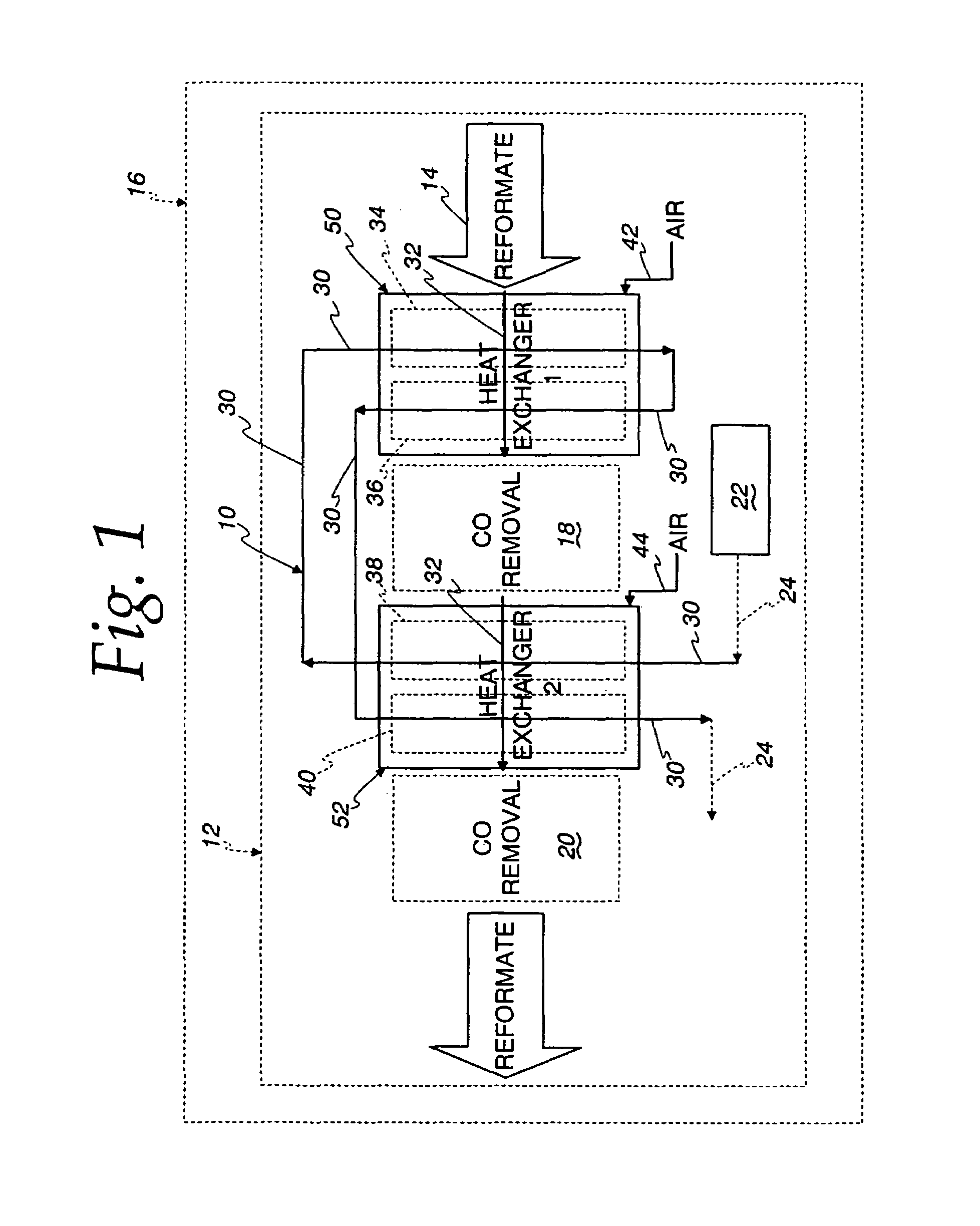
[0028]As seen in FIG. 1 a reformate cooling method and system 10 are provided for use in a fuel processing subsystem, shown schematically at 12, for reducing a level of carbon monoxide (CO) in a reformate flow 14 supplied by the fuel processing subsystem 12 for a proton exchange membrane fuel cell system, shown schematically at 16. The reformate cooling method and system 10 provide an advantageous coolant flow scheme that can allow for simplification of the fuel cell system 16 in comparison to conventional reformate cooling systems.

[0029]The fuel processing subsystem 12 includes a pair of preferential oxidizers 18 and 20 that oxidize the CO carried in the reformate flow 14. Each of the preferential oxidizers 18 and 20 includes a suitable catalyst that requires the reformate flow 14 to be within a desired catalytic reaction temperature range for an optimum catalytic reaction in the preferential oxidizer 18, 20. The preferential oxidizer 20 is located downstream from the preferential ...


PUM

PropertyMeasurementUnit
temperatureaaaaaaaaaa

Abstract

A cooling system (10) is provided for use with a fuel processing subsystem (12) for reducing a level of carbon monoxide in a reformate flow (14) for a proton exchange membrane fuel cell system (16). The fuel processing subsystem (12) includes first and second preferential oxidizers (18, 20) to oxidize the carbon monoxide carried in the reformate flow. The reformate cooling system (10) includes a coolant flow path (30), a reformate flow path (32), and first, second, third, and fourth heat exchanger core portions (34, 36, 38, 40). The core portions (36–40) are arranged in numbered sequence along the reformate flow path (32) with the first and second core portions (34, 36) located upstream of the first preferential oxidizer (18), and the third and fourth core portions (38, 40) located downstream of the first preferential oxidizer (18) and upstream of the second preferential oxidizer (20). The first and second core portions (34, 36) are arranged in numbered sequence along the coolant flow path (30), one of the third and fourth core portions (38, 40) is arranged upstream of the first core portion (34) along the coolant flow path (30), and the other of the third and fourth core portions (38, 40) is arranged downstream of the second core portion along the coolant flow path (30).

Description

FIELD OF THE INVENTION[0001]This invention relates to fuel processing subsystems for fuel cell systems, and in more particular applications, to cooling systems for the reformate fluid flow in fuel processing subsystems for polymer electrolyte membrane fuel cell systems commonly referred to as proton exchange membrane (PEM) fuel cell systems.BACKGROUND OF THE INVENTION[0002]In typical PEM fuel -cell systems, a fuel such as methane or a similar hydrocarbon, is used as a source of the hydrogen for the anode side of the fuel cell. In many systems, particularly those of the stationary power generation type, humidified natural gas and air are chemically converted to a hydrogen-rich gas stream known as reformate by a fuel processing subsystem of the fuel cell system. During this reforming process, the level of carbon monoxide (CO) must be reduced to a low level (typically less than 10 ppm) since the PEM fuel cell membrane is easily poisoned by CO.[0003]The reforming reaction is typically a...

Claims


Application Information

Patent Timeline
Patent Type & Authority Patents(United States)
IPC IPC(8): B01J3/00B01J19/24C01B3/58F28D7/16H01M8/06H01M8/10
CPCB01J19/249C01B3/583F28D7/1615H01M8/0612H01M8/0662Y02E60/50B01J2219/2459B01J2219/2462B01J2219/2495C01B2203/044C01B2203/047C01B2203/066C01B2203/146F28D2021/0043H01M8/0668H01M8/1002B01J2219/2453H01M8/1007H01M8/04C01B3/58F28D7/16
Inventor VALENSA, JEROEN
Owner MODINE MFG CO
Why Eureka
Try Eureka