LED short-circuit detection circuit, LED drive device, LED lighting device, and vehicle

a technology of led lighting devices and detection circuits, applied in the direction of individual semiconductor device testing, instruments, transportation and packaging, etc., can solve the problems of difficult adjustment of detection voltage vth, large management burden during a production process, and large board area, so as to accurately detect an led short circuit

Active Publication Date: 2012-07-19
ROHM CO LTD
View PDF2 Cites 50 Cited by
  • Summary
  • Abstract
  • Description
  • Claims
  • Application Information

AI Technical Summary

Benefits of technology

[0013]In light of the above problems found by the inventors of the present invention, it is an object of the present invention to provide an LED short-circuit detection circuit that is able to accurately detect an LED short-circuit, and an LED drive device, an LED lighting device and a vehicle that use the LED short-circuit detection circuit.

Problems solved by technology

However, in the LED short-circuit detection circuit as the conventional example, adjustment of the detection voltage Vth must be performed considering unevenness of a forward drop voltage VF and a temperature characteristic of the LED, so that there is a problem that a management burden during a production process is large.
Besides, in the LED short-circuit detection circuit as the conventional example, to mount the LED short-circuit detection circuit, many external discrete components are necessary, which brings a problem that a board area becomes large.
Here, when the LED short-circuit detection circuit as the conventional example is simply integrated, there is a problem that the adjustment of the detection voltage Vth becomes hard; and the LED short-circuit detection accuracy deteriorates.

Method used


Image

  • LED short-circuit detection circuit, LED drive device, LED lighting device, and vehicle
  • LED short-circuit detection circuit, LED drive device, LED lighting device, and vehicle
  • LED short-circuit detection circuit, LED drive device, LED lighting device, and vehicle

Examples


Embodiment Construction

[0043]

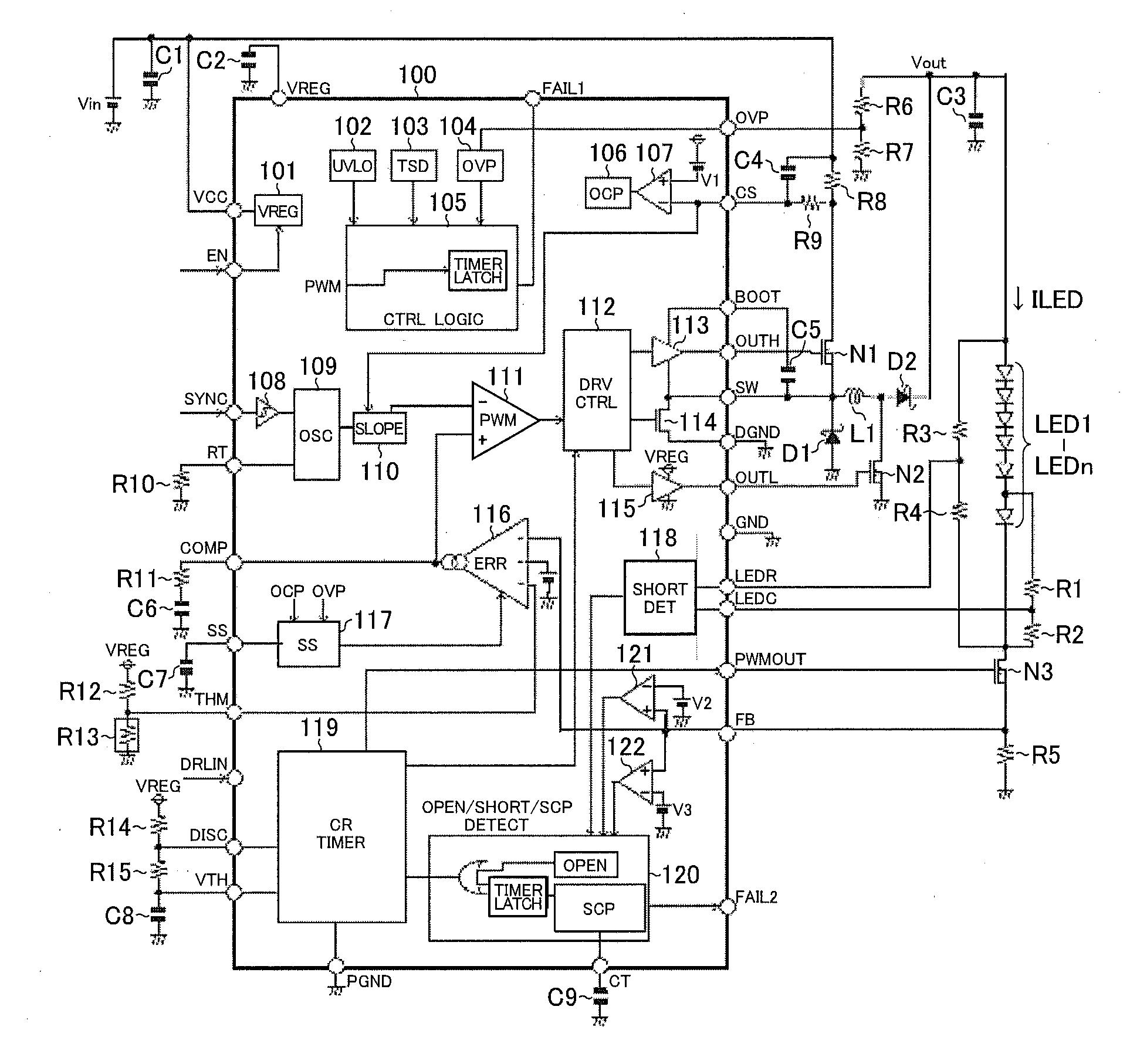
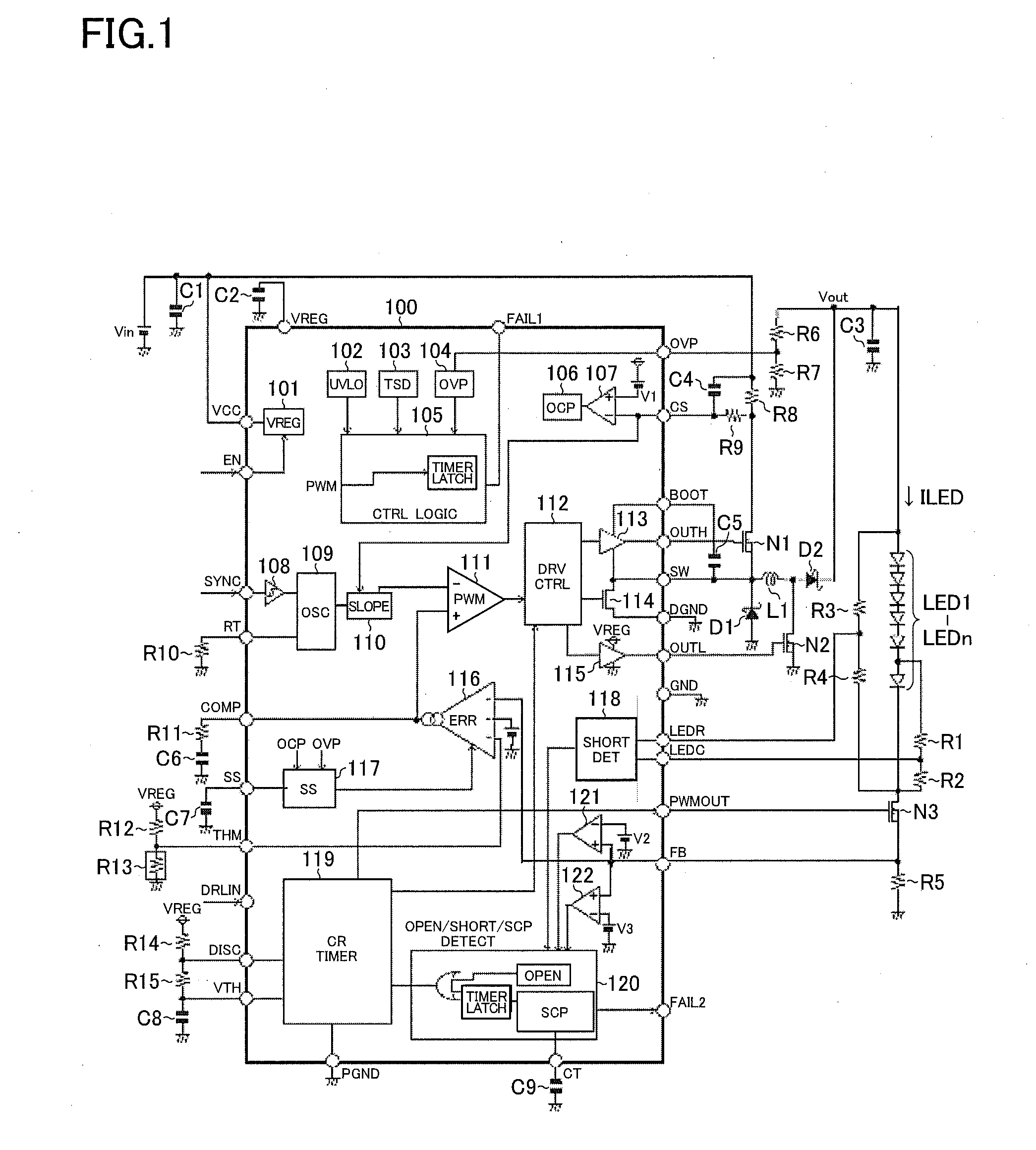
[0044]FIG. 1 is a circuit block diagram showing a first structural example (voltage step-up / down application structural example) of an LED driver IC according to the present invention. An LED driver IC 100 of the present structural example is a semiconductor device which integrates: an internal constant voltage generation portion 101; an UVLO [Under Voltage Lock Out] portion 102; a TSD [Thermal Shut Down] portion 103; an OVP [Over Voltage Protection] portion 104; a control logic portion 105; an OCP [Over Current Protection] portion 106; a comparator 107; a Schmitt trigger 108; an oscillation portion 109; a slope generation portion 110; a PWM [Pulse Width Modulation] comparator 111; a driver control portion 112; an high-side driver 113; an N channel MOS [Metal Oxide Semiconductor] field effect transistor 114; a low-side driver 115; an error lamp 116; a soft start portion 117; an LED short-circuit detection portion 118; a CR timer portion 119; a various trouble detection portion...


PUM


Abstract

An LED short-circuit detection circuit produces an LED short-circuit detection signal by monitoring an LEDC terminal voltage (a first voltage obtained at a chip-to-chip node in a row of LED chips, or a divided voltage thereof) and an LEDR terminal voltage (a second voltage obtained by dividing the end-to-end voltage of the row of LED chips).

Description

CROSS-REFERENCE TO RELATED APPLICATIONS[0001]This application is based on the following Japanese Patent Applications, the content of which is hereby incorporated by reference.[0002][1] No. 2011-004495 (the filing date: Jan. 13, 2011)[0003][2] No. 2011-289358 (the filing date: Dec. 28, 2011)BACKGROUND OF THE INVENTION[0004]1. Field of the Invention[0005]The present invention relates to an LED (Light Emitting Diode) short-circuit detection circuit, an LED drive circuit, an LED lighting device, and a vehicle that use the LED short-circuit detection circuit.[0006]2. Description of Related Art[0007]In a case where a plurality of LEDs are connected in series and are driven, when the LED shorts on one stage, the number of turned-on LEDs decreases by one stage and the brightness of the LED line becomes low as a whole. Especially, in the field of a vehicle lamp, because a brightness shortage is handled as a violation of the law, an LED short-circuit detection circuit is a must.[0008]FIG. 24 ...

Claims


Application Information

Patent Timeline
Patent Type & Authority Applications(United States)
IPC IPC(8): B60Q1/04G01R31/44B60Q1/30B60Q1/44H05B37/02B60Q1/26H05B44/00
CPCB60Q11/005H05B33/0887G01R31/2635G01R31/025H05B45/58G01R31/52H05B45/325
Inventor KATSURA, KOJI
Owner ROHM CO LTD
Why Eureka
Try Eureka