Dimming of LED driver

a technology of led drivers and led bulbs, which is applied in the direction of electroluminescent light sources, electric lighting sources, and use of semiconductors. it can solve the problems of low efficiency of hard switching converters, and generation of relative high level of electromagnetic interferen

Active Publication Date: 2012-07-19
KONINKLIJKE PHILIPS ELECTRONICS NV
View PDF3 Cites 30 Cited by
  • Summary
  • Abstract
  • Description
  • Claims
  • Application Information

AI Technical Summary

Benefits of technology

[0007]It would be desirable to provide an LED driver circuit which provides for stable deep dimming of an LED unit.

Problems solved by technology

Use of hard switching converters has disadvantages in that they do not have a high efficiency, and in that they generate a relative high level of electromagnetic interference, EMI.
A relatively low efficiency of the hard switching converter leads to increased power dissipation at the commonly used high converter frequencies.
As a result, cooling of some converter power components becomes a major problem, which restricts a desired miniaturization of the converter.
Generating a relative high level of EMI means that relative large area has to be reserved for mains filtering, which further restricts miniaturization of the converter.
For very small duty cycles in PWM operation, PWM controlled converters cannot provide a desired stability of the duty cycle.
An unstability of the duty cycle may result in flickering, which is undesirable.

Method used


Image

  • Dimming of LED driver
  • Dimming of LED driver
  • Dimming of LED driver

Examples


Embodiment Construction

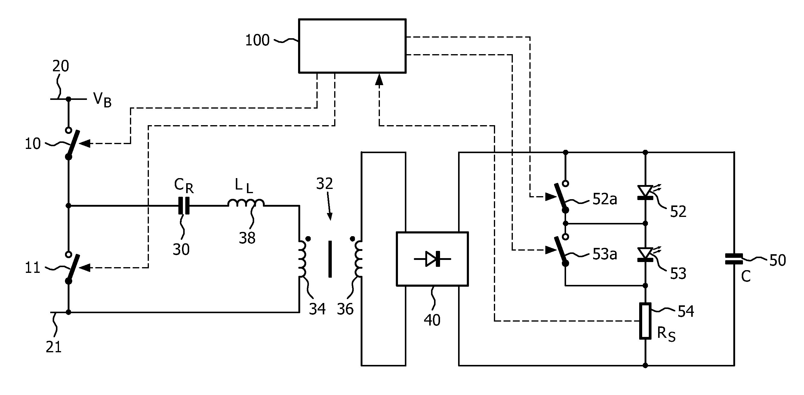
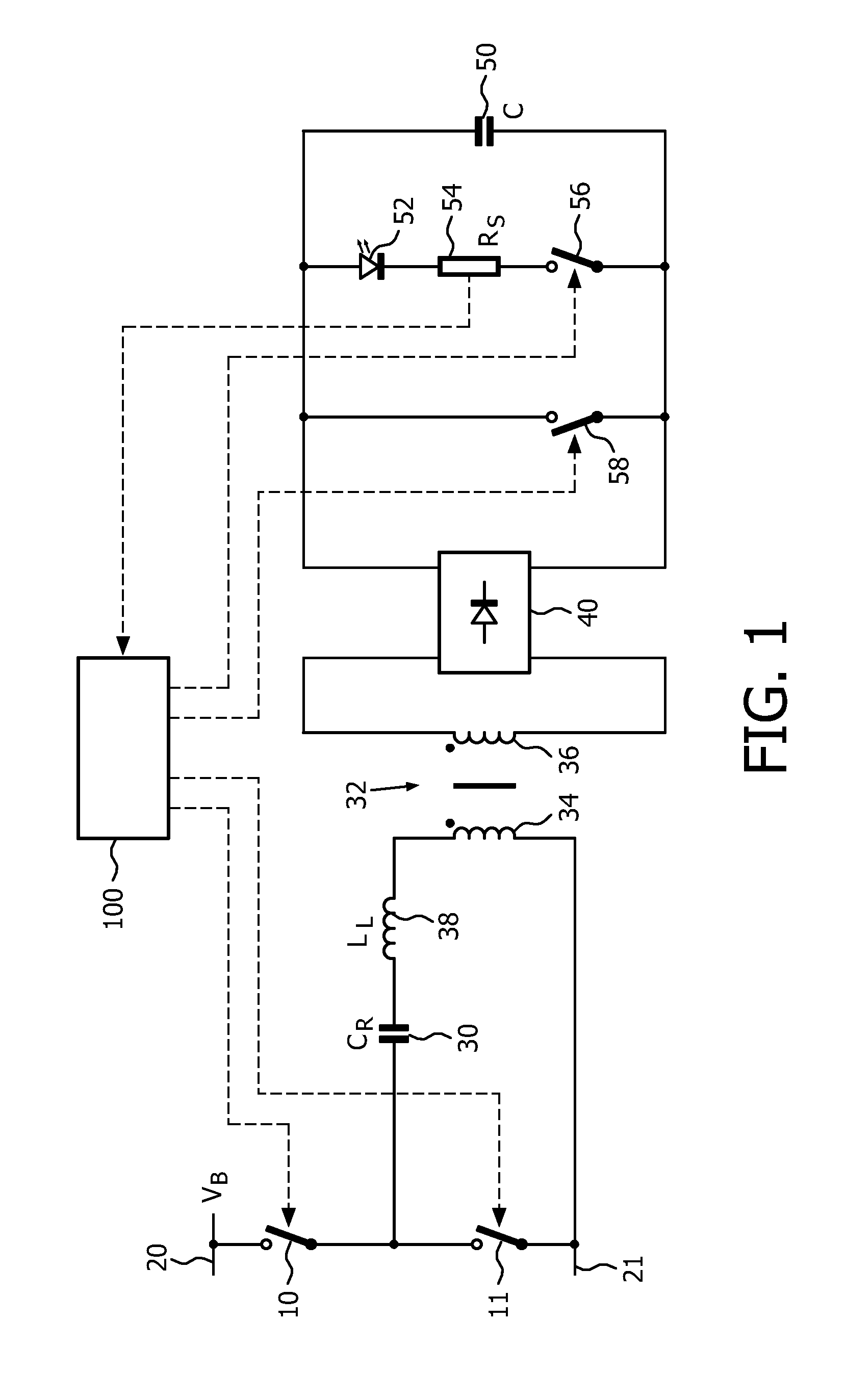
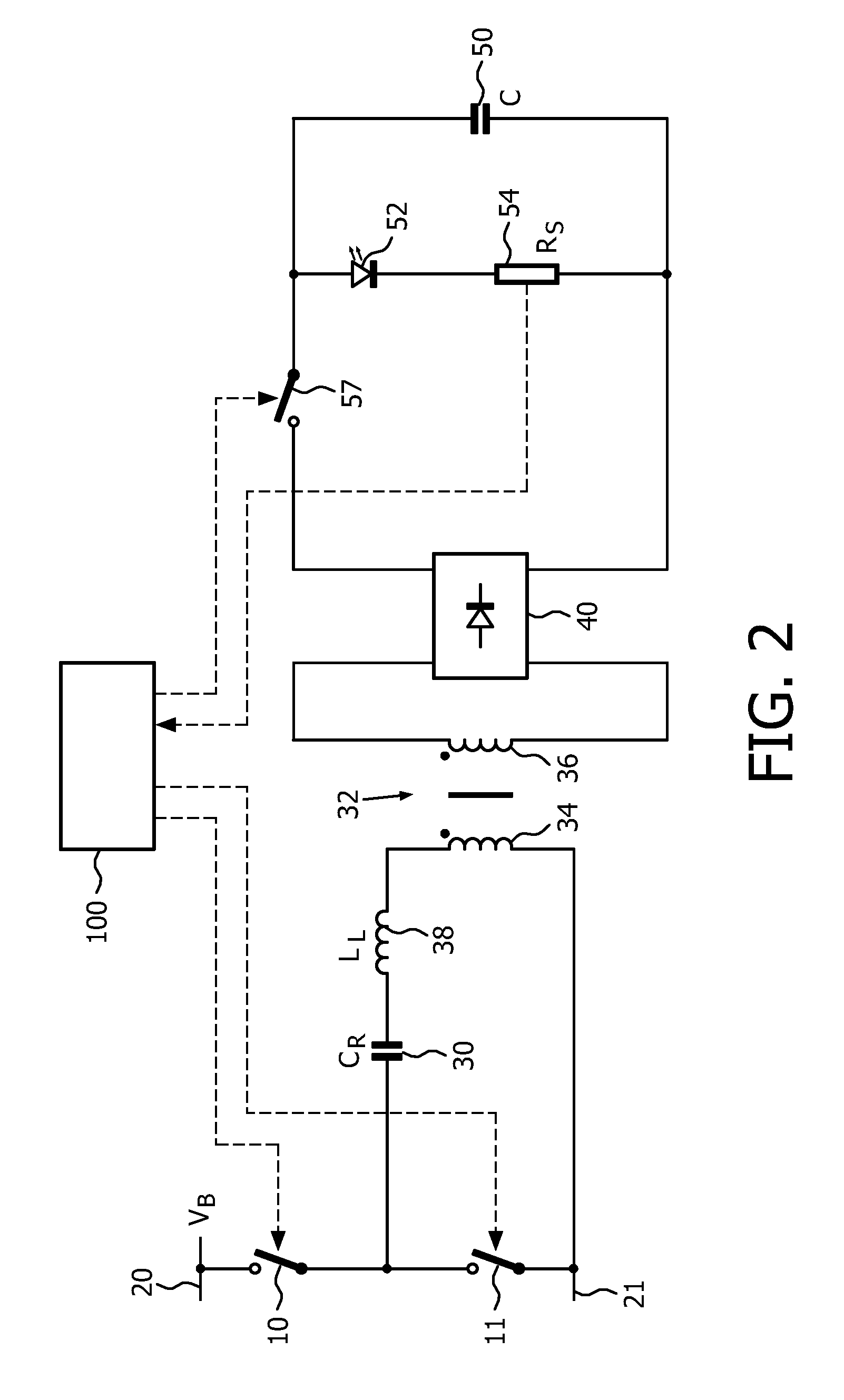
[0025]FIGS. 1, 2, 3 and 4 depict an LED driver circuit comprising a resonant DC-DC converter. The resonant DC-DC converter comprises a switching circuit coupled to a resonant circuit, and a rectifier circuit coupled to the resonant circuit.

[0026]As depicted in FIGS. 1, 2, 3 and 4, the switching circuit of the LED driver circuit comprises a switching circuit, in the embodiment shown a half bridge switching circuit having converter switches 10, 11 coupled in series between input voltage terminals 20, 21 which are configured to receive a DC input voltage VB. Each of the switches 10, 11 may be any suitable kind of electronic switch, e.g. a metal oxide semiconductor field effect transistor, MOSFET, switch. The DC input voltage may be generated by rectification of an AC mains voltage with a rectifier circuit, which may be supplemented with a power factor correction, PFC, circuit. In the art, rectifier circuits as well as PFC circuits are well known in various embodiments, and consequently...


PUM


Abstract

A dimmable LED driver circuit comprises a resonant DC-DC converter coupled to an output circuit. The converter comprises a half bridge or full bridge switching circuit coupled to a resonant circuit. An output of the resonant circuit is rectified and fed to the output circuit. The output circuit may comprise at least one LED series or shunt switch for switching an LED unit on and off. A control circuit controls the switches of the switching circuit at a variable switching frequency. The control circuit is also configured for controlling the switching circuit for amplitude modulating the converter and for pulse-width modulating the converter at a first pulse-width modulation frequency lower than the switching frequency. The control circuit is may further be configured for controlling the switching of the LED switch at a second pulse-width modulation frequency lower than the switching frequency.

Description

FIELD OF THE INVENTION[0001]The invention relates to the field of light emitting diode, LED, drivers, and more specifically to dimming of LED drivers to achieve very low dimming levels.BACKGROUND OF THE INVENTION[0002]LEDs are increasingly used for various illumination applications. Many of such application require an LED driver to be dimmable to vary the amount of light produced by the LED or LEDs. Further, in a combination of LEDs producing light of different colors, where the different colors are mixed to obtain light with a specific color temperature, an LED driver for LEDs of one color or several colors also needs to be dimmable.[0003]Existing converters used for dimmable LED driver purposes are mainly hard switching converters. Use of hard switching converters has disadvantages in that they do not have a high efficiency, and in that they generate a relative high level of electromagnetic interference, EMI.[0004]A relatively low efficiency of the hard switching converter leads t...

Claims


Application Information

Patent Timeline
Patent Type & Authority Applications(United States)
IPC IPC(8): H05B37/02H05B44/00
CPCH05B33/0815Y02B20/348Y02B20/346H05B33/0818H05B45/39H05B45/327Y02B20/30H05B45/3725Y02B20/40
Inventor SNELTEN, JEROENVAN DER VEEN, GEERT WILLEM
Owner KONINKLIJKE PHILIPS ELECTRONICS NV
Why Eureka
Try Eureka