Flop type selection for very large scale integrated circuits

a technology of integrated circuits and flop types, applied in the field of electronic circuits, can solve problems such as min-time problems, subject to race conditions, and give rise to certain limitations

Active Publication Date: 2012-07-19
ORACLE INT CORP
View PDF0 Cites 1 Cited by
  • Summary
  • Abstract
  • Description
  • Claims
  • Application Information

AI Technical Summary

Benefits of technology

[0008]A method for determining flop types for an integrated circuit (IC) on an individual, flop-by-flop basis is disclosed. In one embodiment, the method includes operating a plurality of flop circuits of an IC in a first mode and in a second mode. Each of the plurality of flop circuits includes master and slave latches. In the first mode, the master latch of each of the plurality of flop circuits receives a first clock signal while the slave latch of each of the plurality of flop circuits receives a second clock signal. The clock signals may be aligned such that the master and slave latches are not concurrently transparent. In the second mode, the slave latch receives the second clock signal while the first clock signal is inhibited such that the master latch remains transparent. Based on the results of operating in the first and second modes, it may be determined which of the plurality of flop circuits are to operate as master-slave flip-flops in a subsequent revision of the IC, and which are to operate as pulse flops.
[0009]In one embodiment, a method includes performing a layout of an IC design, which includes arranging master and slave latches of each of a plurality of flops to receive first and second clock signals, respectively. The

Problems solved by technology

The different operational characteristics of flip-flops and pulse flops may make them suitable for certain uses in an IC, but may also give rise to certain limitations.
For example, while some pulse flop designs may be suitable for high-speed signal paths, they can also be subject to a race condition known as the min-time problem, wherein a signal may propagate through two or more serially coupled pulse flops when both are in their transparency phase (e.g., when the pulse is asserted

Method used


Image

  • Flop type selection for very large scale integrated circuits
  • Flop type selection for very large scale integrated circuits
  • Flop type selection for very large scale integrated circuits

Examples


Embodiment Construction

Overview:

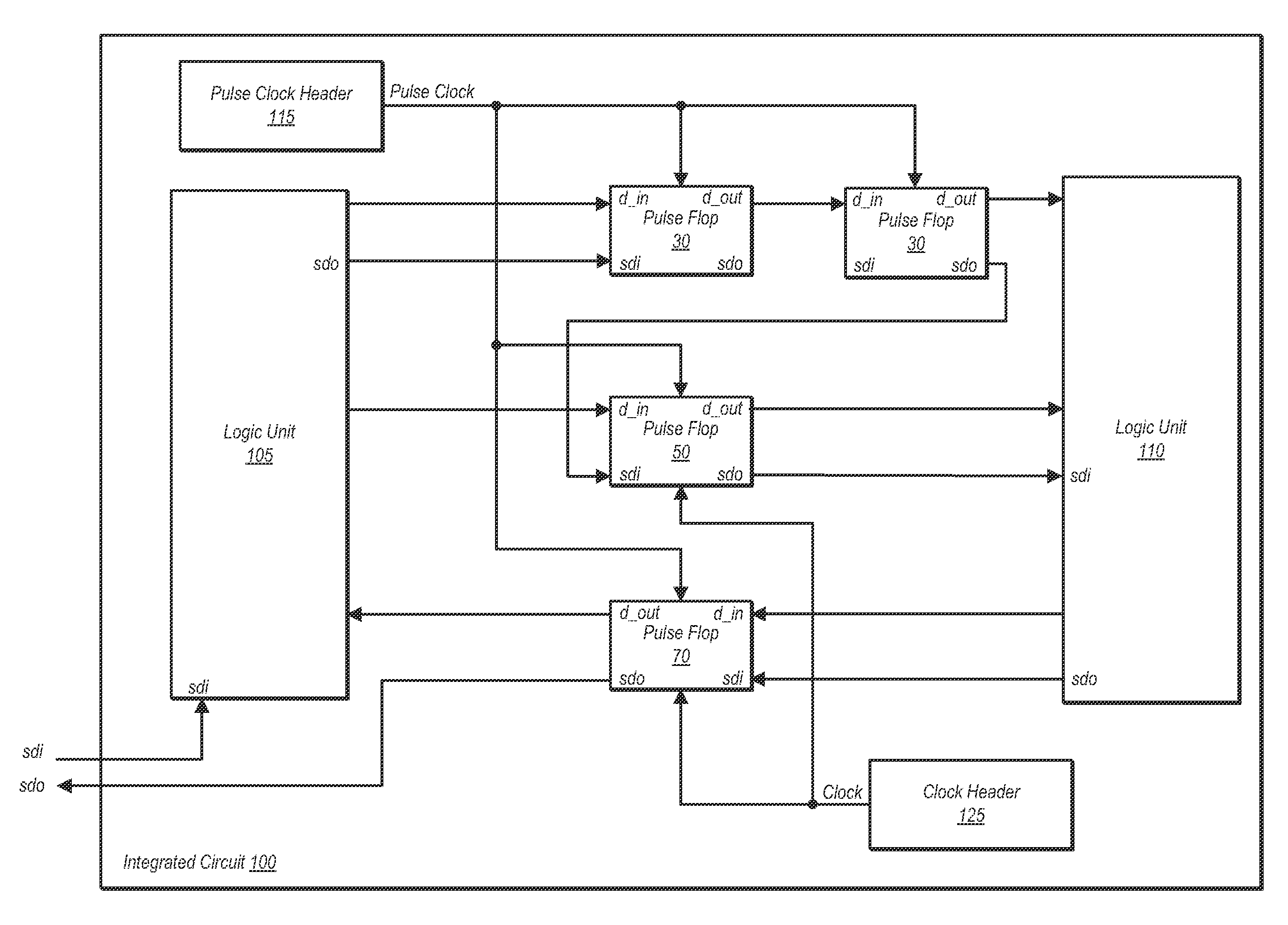
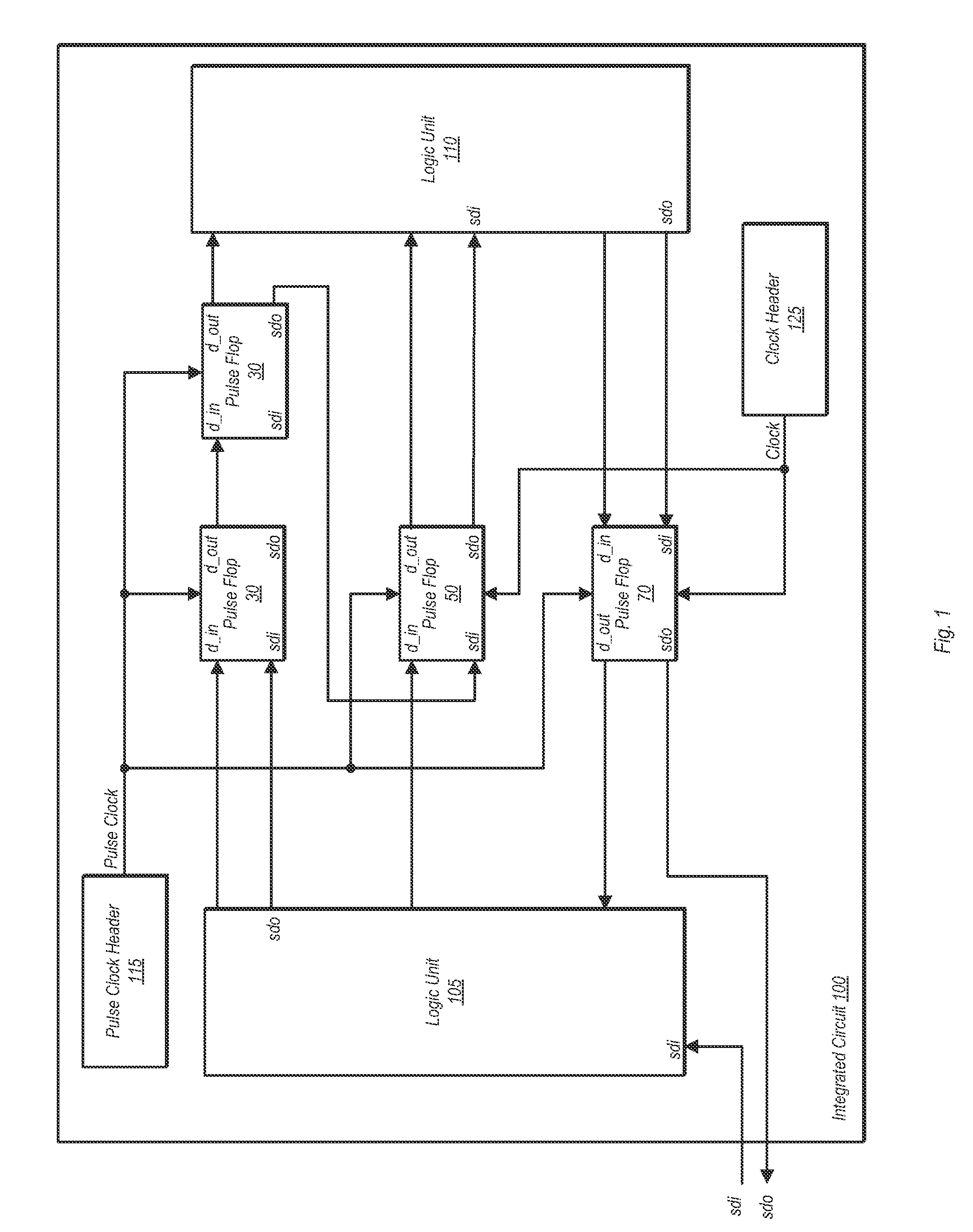
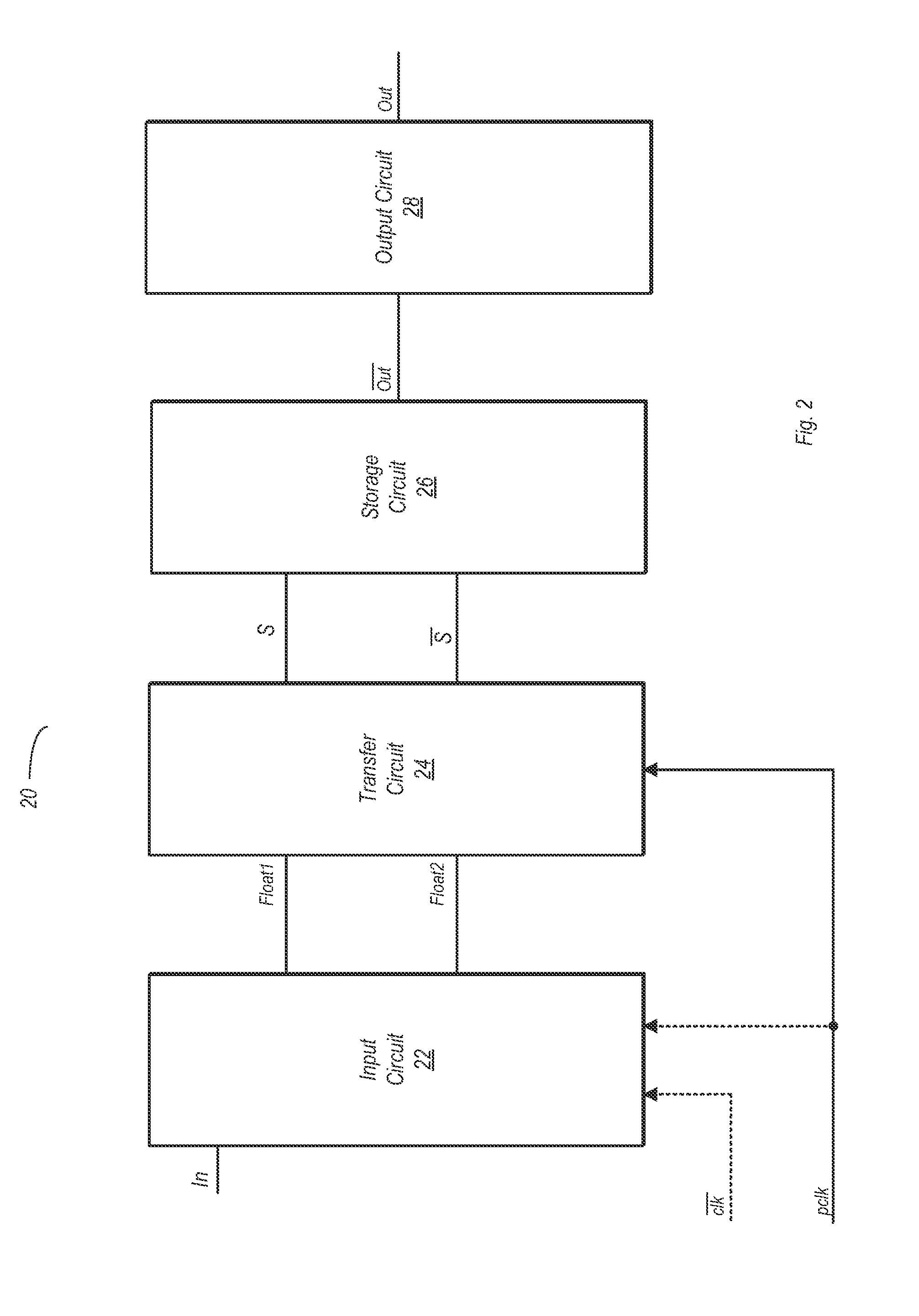
[0025]The present disclosure is directed to a method of determining flop types (e.g., master-slave flip-flop or pulse flop) for certain flop circuits in an integrated circuit (IC) design. As used herein, the term flop circuit (or flop) may refer to one of several different types of storage circuits, including master-slave flip-flops, pulse flops, and latches that are otherwise not part of the former two circuits.

[0026]While some flop circuits in an IC design may be designated as master-slave flip-flops or pulse flops early in the design process, others are sometimes not easily designated as one or the other. As will be explained in further detail below, flops that are designated as non-critical may be implemented as master-slave flip-flops, while those designated as frequency limiters (or ‘F-limiters’) may be implemented as pulse flops. Flops of a third category, designated here as critical flops, are sometimes difficult to determine whether best implemented as a master-sla...


PUM


Abstract

A method for determining flop circuit types includes performing a layout of an IC design including arranging master and slave latches of each of a plurality of flops to receive first and second clock signals, respectively. The initial IC design may then be implemented (e.g., on a silicon substrate). After implementation, the IC may be operated in first and second modes. In the first mode, the master latch of each flop is coupled to receive a first clock signal. In the second mode, the first clock signal is inhibited and the master latch is held transparent. The slave latch of each flop operates according to a second clock signal in both the first and second modes. The method further includes determining, for each flop, whether that flop is to operate as a master-slave flip-flop or as a pulse flop in a subsequent revision of the IC.

Description

BACKGROUND[0001]1. Field of the Invention[0002]This invention relates to electronic circuits, and more particularly, to the selection of flop circuits in an integrated circuit design.[0003]2. Description of the Related Art[0004]Integrated circuits (ICs) may utilize a wide variety of different types of storage circuits. Commonly used storage circuits include master-slave flip-flops and latch circuits. Flip-flops and latches may be widely used to provide temporary storage of data states in an IC, e.g., for storing a state of a signal in transit between a first block of combinational logic and a second block of combinational logic.[0005]Another type of storage circuit used in ICs is a pulse flop. A pulse flop may be formed by converting a single latch circuit to perform a flip-flop function using a pulse clock having a duty cycle of less than 50%. When the pulse clock is asserted (e.g., high), the pulse flop may be transparent, and thus a logic value on an input may be received and pro...

Claims


Application Information

Patent Timeline
IPC IPC(8): H03K3/289G06F17/50
CPCG06F17/505H03K3/0372G06F17/5068G06F30/327G06F30/39
Inventor SMITH, ALAN P.MASLEID, ROBERT P.KONSTADINIDIS, GEORGIOS
Owner ORACLE INT CORP
Why Eureka
Try Eureka