
Monitoring method and system for detecting the torsion along a cable provided with identification tags

a technology of identification tags and monitoring methods, applied in the direction of instruments, force/torque/work measurement apparatus, control, etc., can solve the problem of relatively short typical life of heavy-duty cables

Active Publication Date: 2012-07-19
PRYSMIAN SPA
View PDF3 Cites 12 Cited by
  • Summary
  • Abstract
  • Description
  • Claims
  • Application Information

AI Technical Summary

Benefits of technology

[0014]Due to the mechanical stresses imposed during normal operation, the typical lifetime of a heavy-duty cable is in general relatively short and, depending on the application, can vary from few months to few years. The Applicant has observed that it would be advantageous to provide a monitoring system that permits control of the torsion in an electric cable, in particular in a heavy-duty cable, during its operation. By knowing the temporal evolution of the cable torsional condition, an effective periodic maintenance of the cable can be scheduled and carried out without inconvenience.
[0015]In particular, the Applicant has realized that it would be advantageous to monitor in situ the actual deployment of a cable by placing a monitoring system in correspondence to parts of the mobile equipment where the cable is expected to undergo significant torsional stresses.
[0017]The Applicant has realised that it would be particularly advantageous to record the time variation of cable torsion for at least one longitudinal cable section, i.e. the variation of torsional state of cable sections along the length thereof, which can damage the cable by fatigue and shorten its lifetime.

Problems solved by technology

Due to the mechanical stresses imposed during normal operation, the typical lifetime of a heavy-duty cable is in general relatively short and, depending on the application, can vary from few months to few years.

Method used


Image

  • Monitoring method and system for detecting the torsion along a cable provided with identification tags
  • Monitoring method and system for detecting the torsion along a cable provided with identification tags
  • Monitoring method and system for detecting the torsion along a cable provided with identification tags

Examples


Embodiment Construction

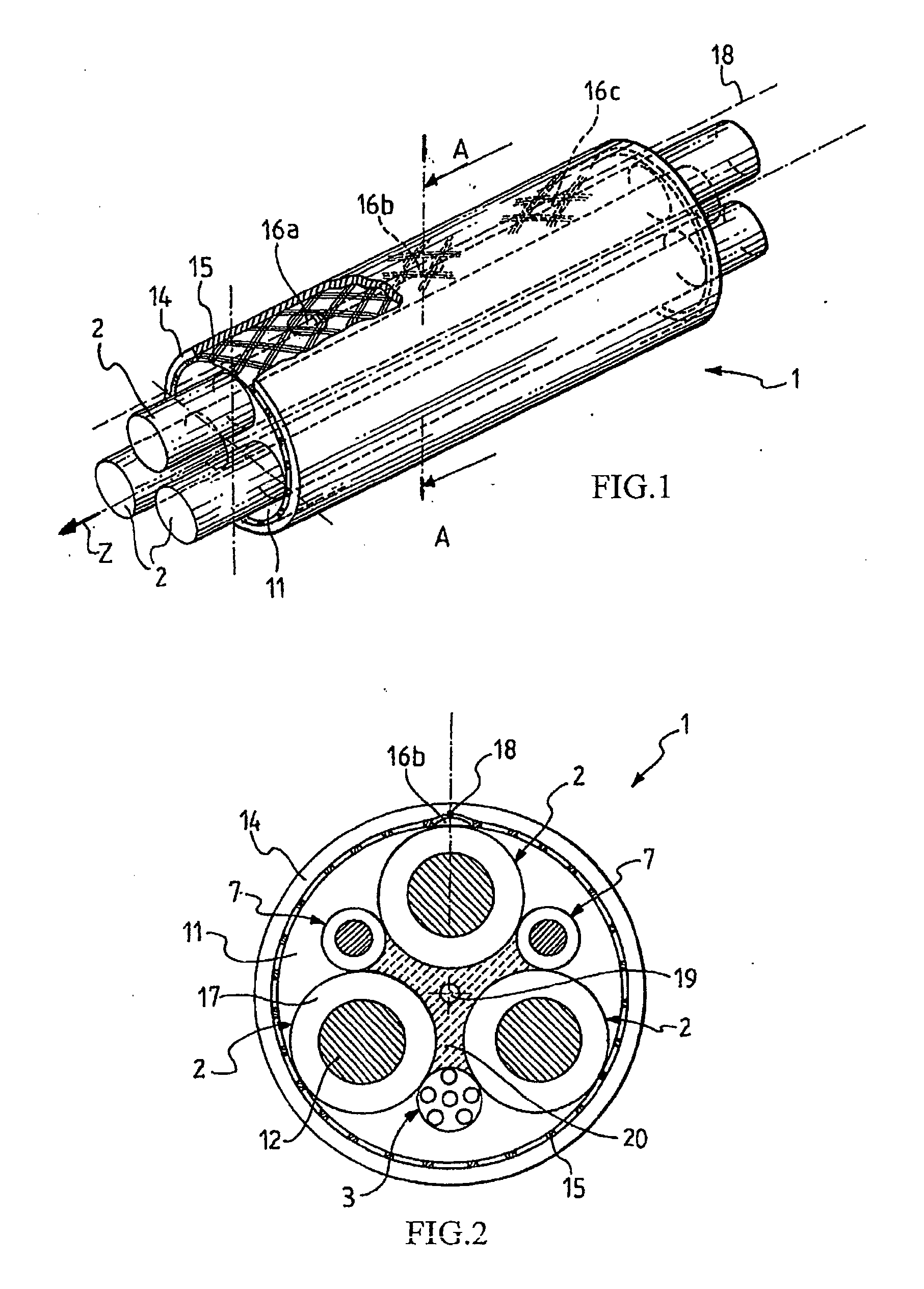
[0039]FIG. 1 is a schematic perspective view of an electric cable, in particular a heavy-duty cable, according to an embodiment of the present invention. FIG. 2 schematically illustrates a cross-sectional view of the electric cable of FIG. 1 taken along the A-A line. Not all details of the cable internal structure shown in FIG. 2 are illustrated in FIG. 1, to improve clarity of the latter figure. Cable 1 extends along a central longitudinal axis Z and comprises three cores 2 radially arranged about a central longitudinal axis Z. For instance, the cores 2 provide three-phase power transmission. Each core 2 can have a conventional structure, for example it comprises an electrical conductor 12, such as a copper conductor formed by a bundle of tinned copper electrical wires stranded together according to conventional methods. In radial external position with respect to each electrical conductor 12, an insulating layer 17 is provided. In some cable constructions, the electrical conductor...


PUM


Abstract

A method for monitoring the torsion of a cable includes the steps of: providing a cable having an outer surface and extending along a longitudinal direction, the cable being provided with at least one identification tag, preferably an RFID tag, arranged in a tag angular position in a cross-sectional plane taken transverse to the longitudinal direction, the at least one tag storing a tag identification code and being capable of transmitting a tag electromagnetic signal; interrogating the at least one identification tag to receive the tag electromagnetic signal, and detecting the tag electromagnetic signal, wherein the step of detecting the tag electromagnetic signal includes the step of reading the tag identification code and determining the tag angular position of the at least one identification tag. A torsion monitoring system of a cable includes at least one identification tag.

Description

FIELD OF THE INVENTION[0001]The present invention relates to a monitoring method and system for detecting the mechanical torsion of a cable.BACKGROUND OF THE INVENTION[0002]Cables for heavy-duty applications and in particular for mobile installations, such as mobile harbour cranes, ship-to-shore container cranes, ship un-loaders, spreaders, mining and tunnelling equipment, and windmill and windfarm are specifically designed to withstand harsh environment conditions and high mechanical stresses, such as tensile forces and torques. Within the present description, we will in general refer to heavy-duty cables, when referring to cables for heavy-duty applications and in particular, but not exclusively, for mobile installations.[0003]An example of heavy-duty electric cable is provided in DE patent application No. 3934718, which describes an armoured trailing cable for shearer loaders in mines.[0004]WO 01 / 78086 discloses an electric cable in particular for use in a pick-up system such as ...

Claims


Application Information

Patent Timeline
IPC IPC(8): G06K7/01G08C17/02
CPCG01L5/047B66C13/12D07B1/145G01L3/00D07B2301/251
Inventor SARCHI, DAVIDEKNUEPFER, BERNDCOLETTA, GIACOMOCARL, ARND-GUENTHERKEMNITZ, CARSTENGASPARI, ROBERTOKITTEL, THOMASEWALD, REINER
Owner PRYSMIAN SPA
Learn More