Surface mount device multiple-band antenna module

Active Publication Date: 2012-07-19
CIROCOMM TECH CORP +1
View PDF5 Cites 14 Cited by
  • Summary
  • Abstract
  • Description
  • Claims
  • Application Information

AI Technical Summary

Benefits of technology

[0007]The objective of the present invention aims to the above-mentioned problem and thus provides a surface mount device multiple-band

Problems solved by technology

However, due to the size of the antenna, the portable ele

Method used


Image

  • Surface mount device multiple-band antenna module
  • Surface mount device multiple-band antenna module
  • Surface mount device multiple-band antenna module

Examples


Example

[0022]A detailed description of the present invention will be made with reference to the accompanying drawings.

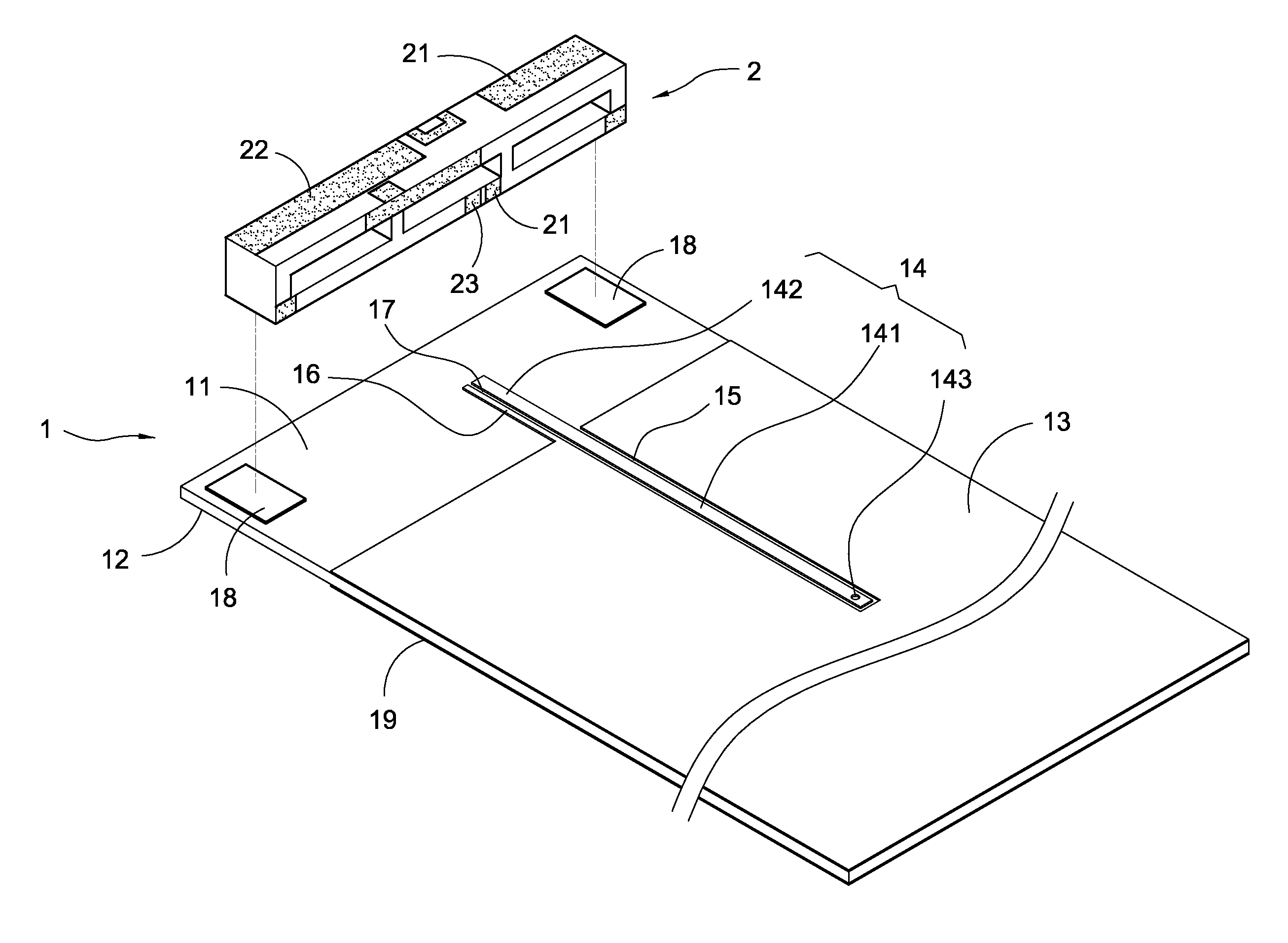
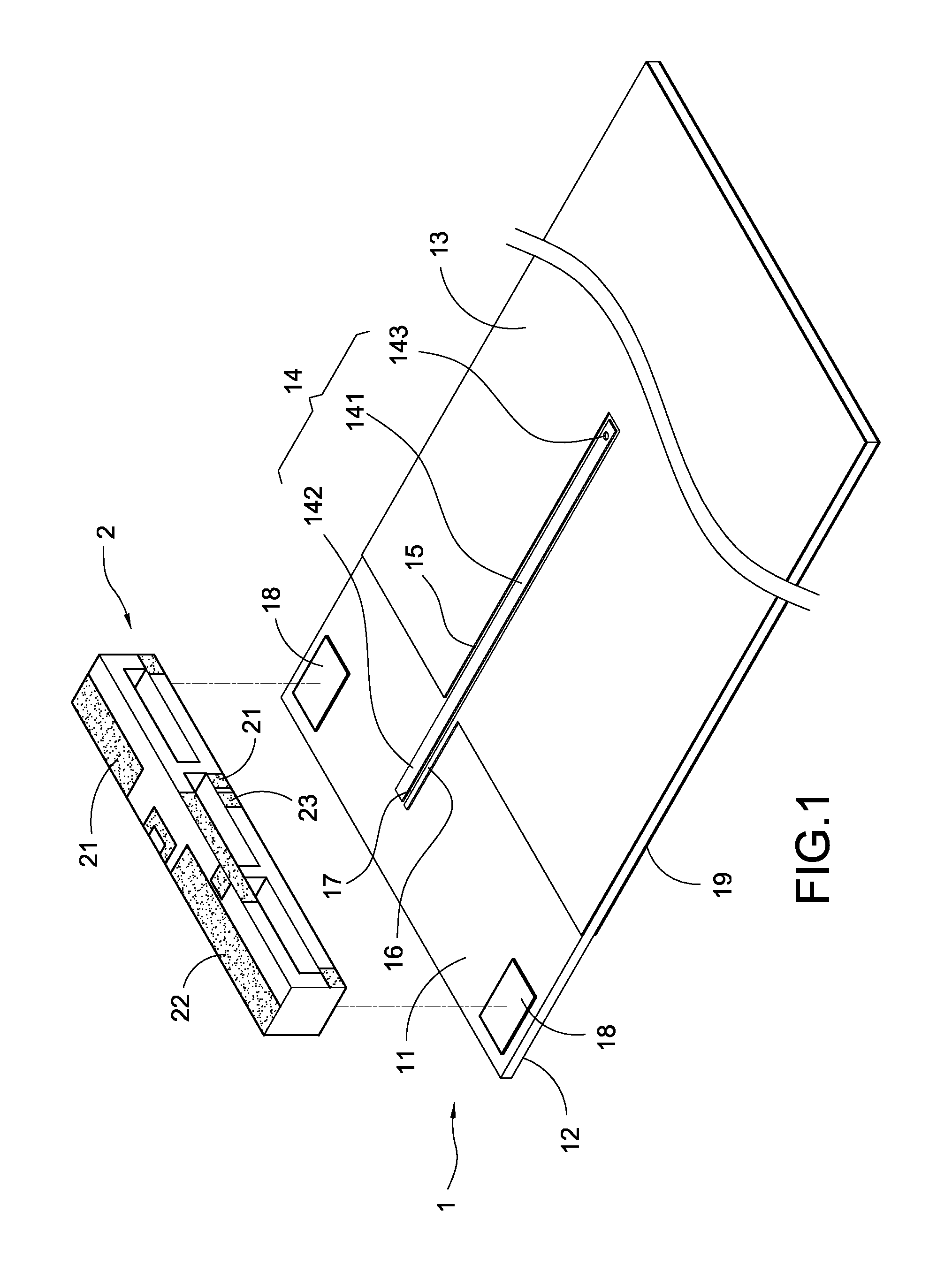
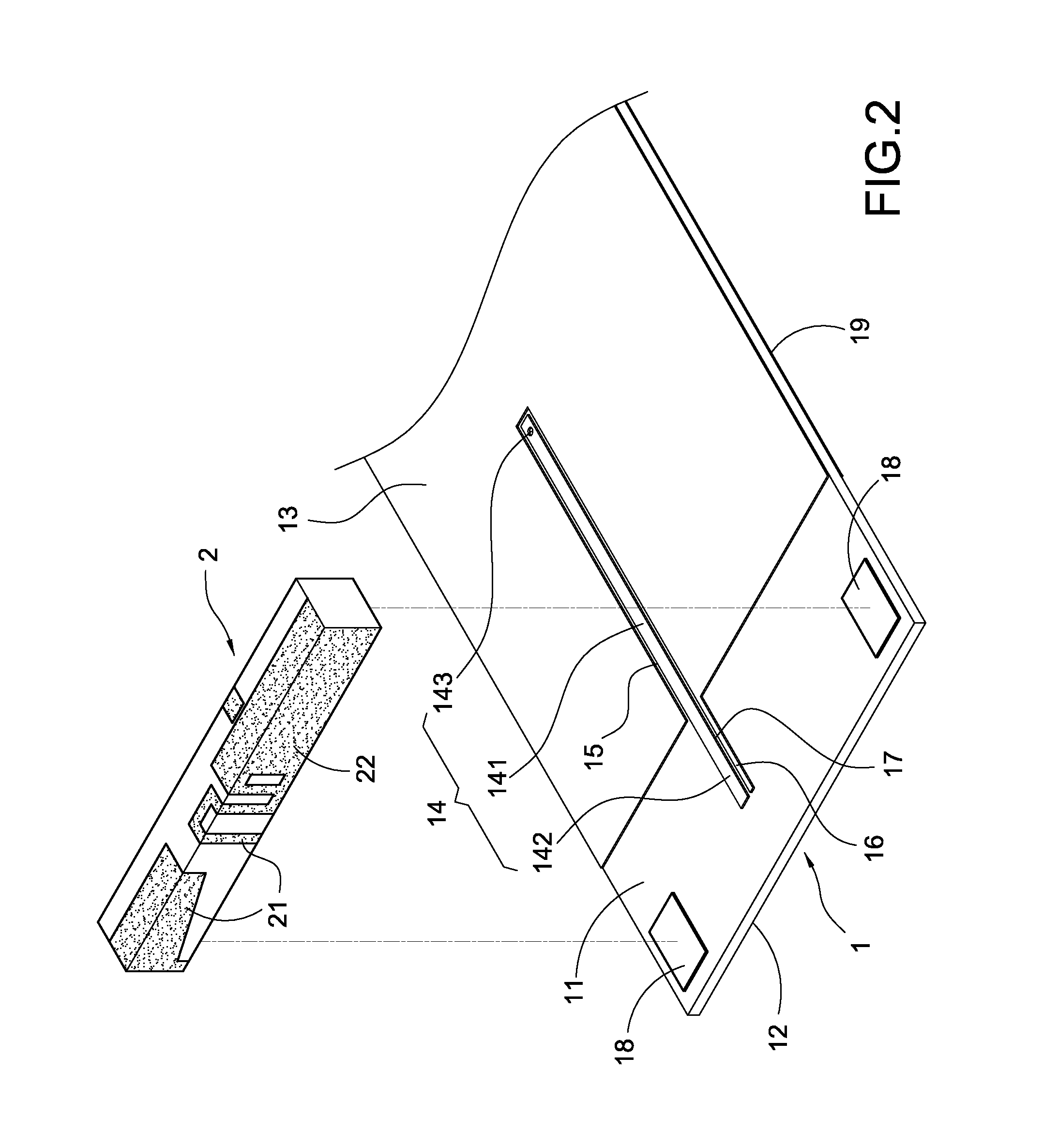
[0023]As FIG. 1 to FIG. 4, the multiple-band antenna module of the present invention mainly includes a substrate 1 and a carrier 2.

[0024]The substrate 1 has a first surface 11 and a second surface 12. The first surface 11 has a first grounding metal surface 13 and a first micro-strip line 14. The first micro-strip line 14 has a front section 141 and a rear section 142. The front section 141 has a through hole 143. The front section 141 of the first micro-strip line 14 extends into the first grounding metal surface 13. An interval 15 is formed between the front section 141 and the first grounding metal surface 13. The first grounding metal surface 13 has a second micro-strip line 16 connected thereto. The second micro-strip line 16 is parallel to the rear section 142 of the first micro-strip line 14. A space 17 is formed between the rear section 142 of the first micro-strip ...


PUM


Abstract

A surface mount device multiple-band antenna module includes a substrate and a carrier. The substrate has a first grounding metal surface and a first micro-strip line on a side thereof. The first grounding metal surface has a second micro-strip line connected thereto. There is a space between the first micro-strip line and the second micro-strip line. The substrate has a second grounding metal surface on the other side thereof The carrier is made of ceramic material with high dielectric constant, which has a first radiative metal portion, a second radiative metal portion and a third radiative metal portion. The carrier is electrically connected with the substrate. The joint of the first radiative metal portion and the second radiative metal portion is electrically connected to the first micro-strip line. The third radiative metal portion is electrically connected to the second micro-strip line. Thus, the multiple-band antenna module is obtained.

Description

BACKGROUND OF THE INVENTION[0001]1. Field of the Invention[0002]This invention relates to an antenna, in particularly to a multiple-band antenna module having higher gain.[0003]2. Description of Related Art[0004]As wireless communication technology keeps developing, the trend in the portable electronic devices like laptop computer, mobile phone, personal digital assistant (PDA) is toward lighter and thinner. Therefore, the antenna in the portable electronic devices for transmitting and receiving electromagnetic wave signals has the need of downsizing or reforming to meet the trend.[0005]The conventional multiple-band antenna such as a planar inverted-F antenna (PIFA) is generated from a two dimensional design. The PIFA can be provided from a printed circuit board (PCB) which has copper foil to be processed into a two dimensional shape, or can be provided as a three dimensional design from metal sheet forming processes.[0006]The PIFA has the two dimensional planar-shaped copper foils...

Claims


Application Information

Patent Timeline
IPC IPC(8): H01Q1/38H01Q5/371
CPCH01Q1/243H01Q5/371H01Q9/42
Inventor YANG, TSAI-YIWU, CHIA-TSUNG
Owner CIROCOMM TECH CORP
Why Eureka
Try Eureka