Thermal-assisted-magnetic-recording head and magnetic recording system equipped with the same

Inactive Publication Date: 2012-07-19
HITACHI LTD
View PDF2 Cites 19 Cited by
  • Summary
  • Abstract
  • Description
  • Claims
  • Application Information

AI Technical Summary

Benefits of technology

[0024]According to an aspect of the present invention, a recording region of a magnetic recording medium can be locally heated by emitting

Problems solved by technology

For this reason, in the case where the light directly enters the core having the width and the thickness in the submicron order, total optical propagation efficiency is low due to a large coupling loss of the light undesirably.
This requires increase in the output light power of the optical source for implementing the thermally assisted magnetic recording, and results in increase in the power consumption in the whole magnetic recording system and increase in the temperature within the apparatus.
Particularly, increase in the temperature leads to reduction in performance of the magnetic recor

Method used


Image

  • Thermal-assisted-magnetic-recording head and magnetic recording system equipped with the same
  • Thermal-assisted-magnetic-recording head and magnetic recording system equipped with the same
  • Thermal-assisted-magnetic-recording head and magnetic recording system equipped with the same

Examples


embodiment 1

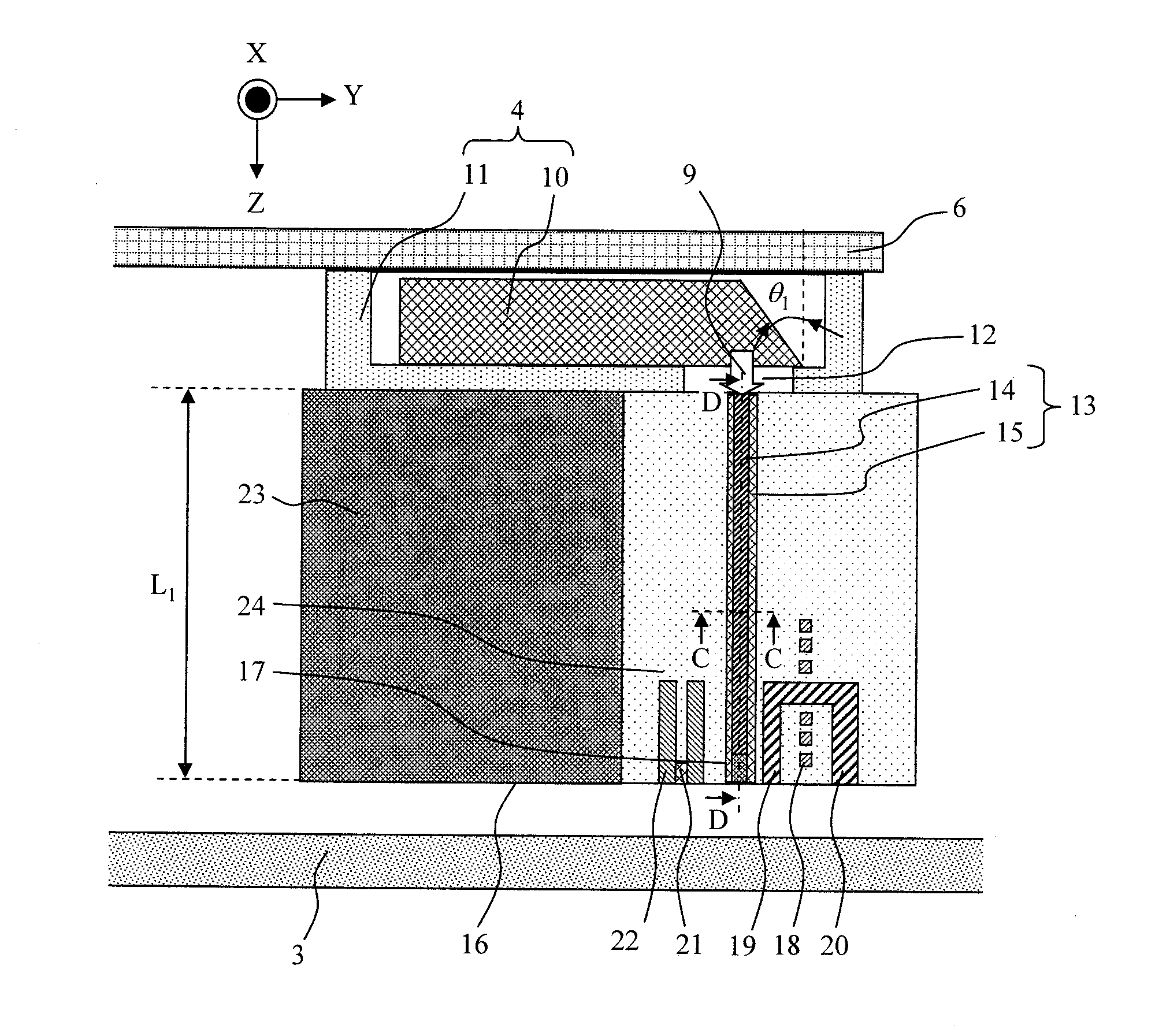
[0061]A magnetic recording system including a highly efficient optical integrated mechanism according to the present invention is described with reference to FIG. 4, FIG. 5 and FIG. 1. FIG. 4 is a perspective view showing an example of a magnetic recording system according to the present invention, with an upper cover removed from a housing 1. FIG. 5 is a cross-sectional view taken along a line A-A of FIG. 4. FIG. 1 is a cross-sectional view of a circumference of a magnetic head comprising a spot size converter, which corresponds to FIG. 5 showing enlarged regions B1-B2-B3-B4.

[0062]As shown in FIG. 4, a magnetic head 5 is fixed to a suspension 6 in such a manner that the position thereof is moved by a voice coil motor 7. A magnetic recording medium 3 rotates by being fixed to a spindle 2 which is driven by a motor in a rotatable mariner. As shown in FIG. 1, ABS (Air Bearing Surface) is formed at a magnetic head bottom surface 16 to generate a negative pressure between the magnetic r...

embodiment 2

[0109]Next, description is made about a waveguide a portion serving to couple the incident light 9 and flatten the wavefront of the propagating light includes a core and a clad only, but no a rectangular portion in which a cover layer 15 made of a material having a refractive index lower than those of a core 14 and a clad material 24 is formed at upper and lower sides (top and bottom as viewed in Y direction) of the core like Embodiment 1.

[0110]FIG. 19A is a cross sectional view of a spot size converter according to the present invention in a direction perpendicular to a light propagation direction, and FIG. 19B is a cross sectional view of the spot size converter in a direction along the light propagation direction. As shown, a thin core 25 may be formed on a side of the light emitting core instead of forming a rectangular portion on top or sides of the taper portion. An optical waveguide comprising a core and a clad and having effects of coupling with the incident light 9 and flat...


PUM


Abstract

Provided is a thermal-assisted-magnetic-recording head capable of irradiating a magnetic recording medium with light with a spot size reduced on the submicron order with high utilization efficiency. A spot size converter 13 for guiding light emitted from an optical source 4 into a magnetic head is provided at a position adjacent to a magnetic main pole 19 in the magnetic head. In the spot size converter 13, a cover layer 15 having a lower refractive index than those of a core 14 and a clad material 24 is formed between the core 14 and the clad 15 and has a shape composed of a shape substantially rectangular in a light traveling direction and a taper shape having a width increasing toward the bottom surface of the magnetic head.

Description

TECHNICAL FIELD[0001]The present invention relates to a thermal-assisted-magnetic-recording head and a magnetic recording system equipped with the thermal-assisted-magnetic-recording head.BACKGROUND ART[0002]The information recording density of magnetic recording systems has been increasing steadily, and the size of a magnetic recording mark per bit has been becoming smaller and smaller. So far, the recording bit size in the magnetic recording system has been mainly reduced by reducing the size of a magnetic recording head and magnetic particles used for a magnetic recording medium. However, since the magnetic recording density exceeded 1 Tbit / inch2, there has been a concern that the magnetic information recorded on the magnetic recording medium may be lost at room temperature due to an influence of thermal fluctuation. To prevent this, a coercive force of the magnetic recording medium needs to be increased. Unfortunately, the magnitude of the magnetic field that can be generated by...

Claims


Application Information

Patent Timeline
IPC IPC(8): G11B13/08G11B13/04
CPCG11B5/314G11B2005/0021G11B2005/001G11B5/6088
Inventor IWANABE, YASUHIKOMATSUMOTO, TAKUYAMIYAMOTO, HARUKAZU
Owner HITACHI LTD
Why Eureka
Try Eureka