
Composite nuclear fuel pellet

a nuclear fuel and pellet technology, applied in the direction of nuclear elements, reactor fuel susbtance, greenhouse gas reduction, etc., can solve the problems of inability to achieve the desired additional energy production of coal, inability to meet the requirements of nuclear fuel production, etc., to achieve the effect of higher thermal conductivity

Inactive Publication Date: 2012-07-19
UT BATTELLE LLC
View PDF1 Cites 29 Cited by
  • Summary
  • Abstract
  • Description
  • Claims
  • Application Information

AI Technical Summary

Benefits of technology

[0009]A composite nuclear fuel pellet that may have advantages over existing UO2 fuel is described, and a method of making a composite nuclear fuel pellet is also disclosed. The composite nuclear fuel pellet comprises a composite body including a UO2 matrix and a plurality of high aspect ratio particles dispersed therein, where the high aspect ratio particles have a higher thermal conductivity than that of the UO2 matrix.
[0010]The method of making a composite nuclear fuel pellet entails combining UO2 powder with a predetermined amount of high aspect ratio part

Problems solved by technology

A separate but very much related problem is greenhouse gas production and renewable energy.
However, coal is a finite resource, and it is a major contributor to anthropogenic greenhouse gas production.
For these reasons, coal is not seen as a desirable source of additional energy production.
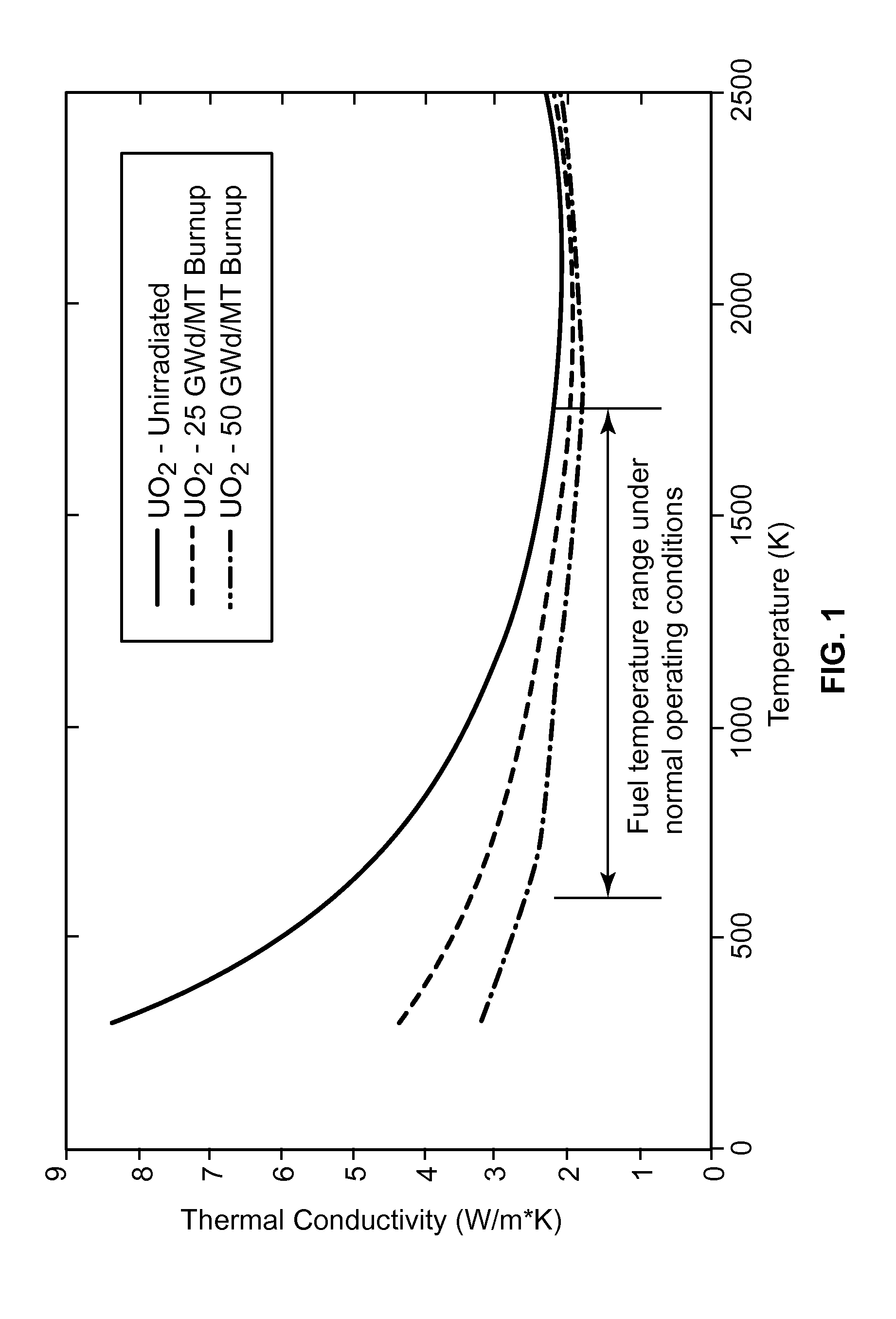
Although chemically stable and inexpensive to manufacture, UO2 fuel is limited by its low thermal conductivity, which is ˜2.5 W / m·K at 1500° K for fresh fuel and decreases as the fuel is burned, as indicated in FIG. 1.
This relationship limits the rate at which heat energy can be removed from the fuel and thus limits the rate of power generation within the fuel.
Although uranium metal has been successfully used in fast reactors with liquid sodium as a coolant, it is unsuitable for use in water reactors since uranium metal reacts strongly with water.
Both of these types of fuels are more expensive to make, are chemically more reactive, and can react with water at operating temperatures.

Method used


Image

  • Composite nuclear fuel pellet
  • Composite nuclear fuel pellet
  • Composite nuclear fuel pellet

Examples


Embodiment Construction

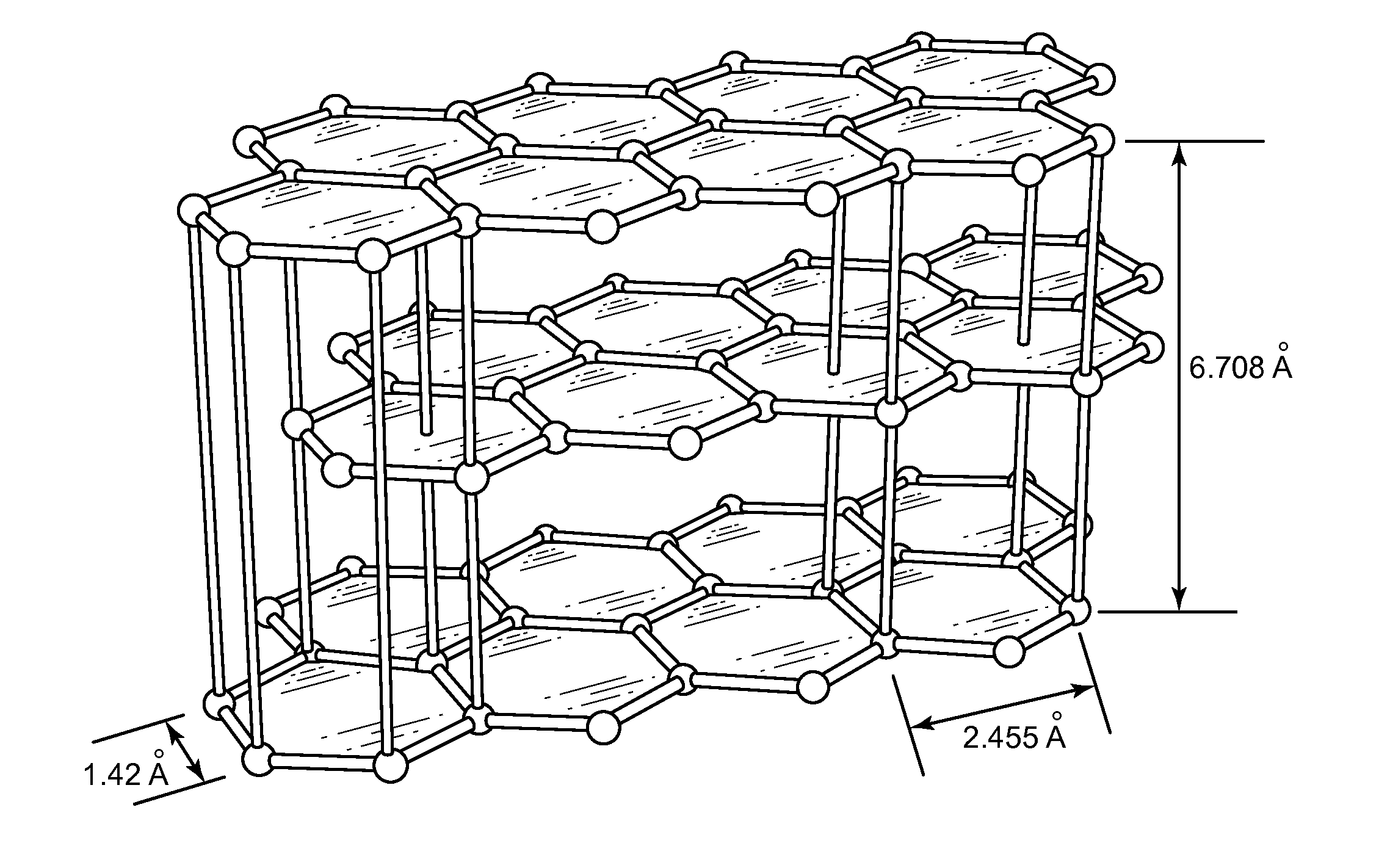
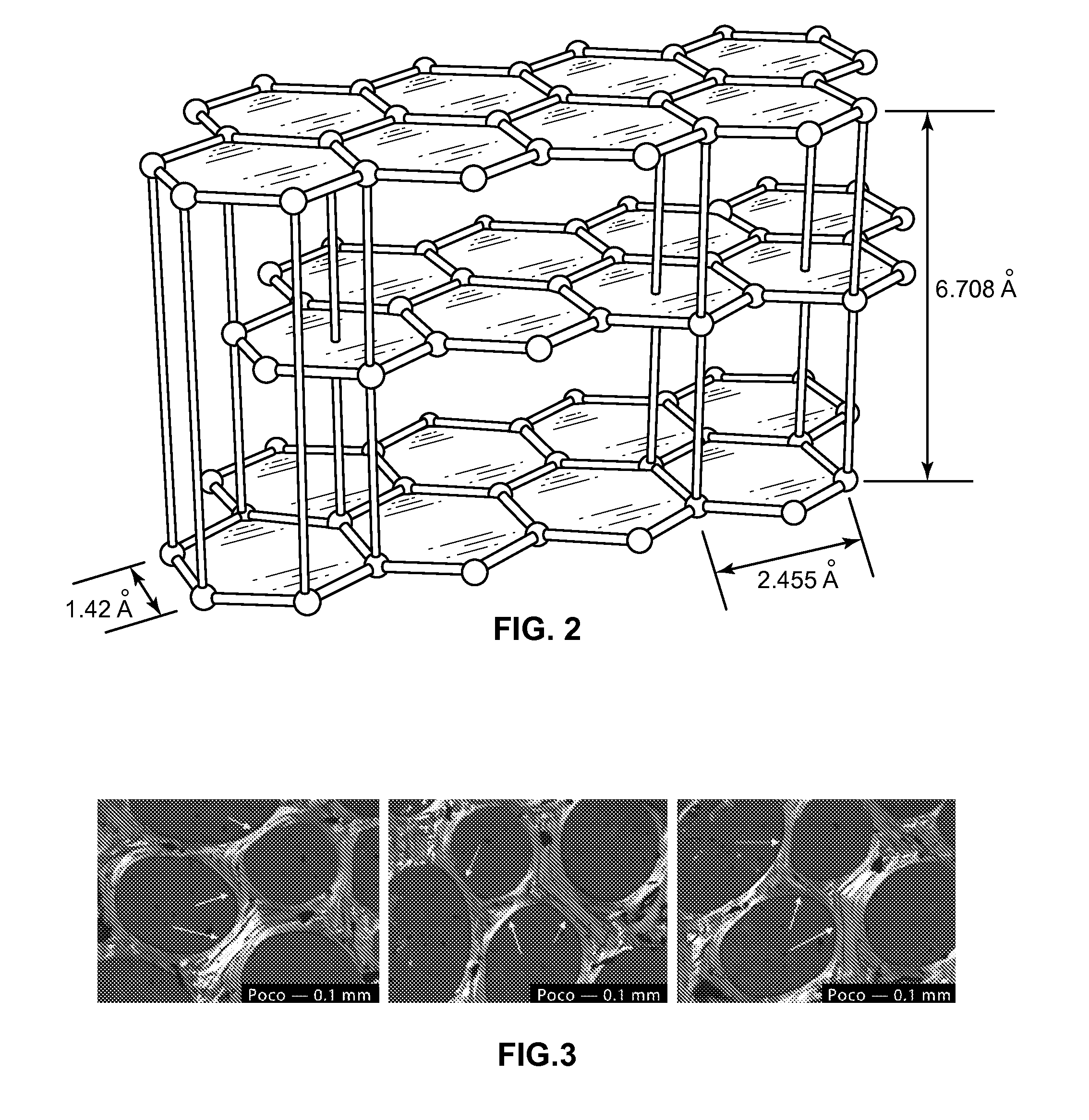
[0027]Computer simulations suggest that the thermal conductivity of UO2 nuclear fuel may be increased by adding high aspect ratio fibers of a thermally conductive material, such as graphitic carbon, to the UO2 fuel during the manufacturing process. At reactor operating temperatures, UO2 has a very low thermal conductivity (<5 W / m·K), which decreases with increasing fuel burnup. This low thermal conductivity limits the rate at which energy can be removed from the fuel, thus limiting the total integrated reactor power. An increase in the thermal conductivity of the fuel may result in a cooler fuel that experiences significantly less damage, thus allowing higher burn-up ratios. Nuclear reactors may also be able to operate at higher power levels (in some plants, in excess of 10% higher) thus decreasing the overall cost of electricity and the number of new electrical generating plants needed to meet demand. Also, higher U-235 enrichments (current U-235 enrichment of nuclear fuel is limit...


PUM

PropertyMeasurementUnit
Fractionaaaaaaaaaa
Fractionaaaaaaaaaa
Timeaaaaaaaaaa

Abstract

A composite nuclear fuel pellet comprises a composite body including a UO2 matrix and a plurality of high aspect ratio particies dispersed therein, where the high aspect ratio particies have a thermal conductivity higher than that of the UO2 matrix. A method of making a composite nuclear fuel pellet includes combining UO2 powder with a predetermined amount of high aspect ratio particles to form a combined powder, the high aspect ratio particles having a thermal conductivity higher than that of the UO2 powder; mixing the combined powder in a solvent to disperse the high aspect ratio particles in the UO2 powder; evaporating the solvent to form a dry mixture comprising the high aspect ratio particles dispersed in the UO2 powder; pressing the dry mixture to form a green body; and sintering the green body to form the composite fuel pellet.

Description

RELATED APPLICATION[0001]The present patent document claims the benefit of the filing date under 35 U.S.C. §119(e) of U.S. Provisional Patent Application Ser. No. 61 / 230,014, filed Jul. 30, 2009, which is hereby incorporated by reference.FEDERALLY SPONSORED RESEARCH AND DEVELOPMENT[0002]This invention was made with government support under Contract No. DE-AC05-00OR22725 awarded by the U.S. Department of Energy. The government has certain rights in the invention.TECHNICAL FIELD[0003]The present disclosure is directed generally to uranium oxide nuclear fuel and more particularly to a composite nuclear fuel pellet with enhanced thermal conductivity.BACKGROUND[0004]The economical production of electrical energy is recognized as being a vital part of our high standard of living as well as our national defense. The clean, efficient production of energy is necessary for a strong economy. A separate but very much related problem is greenhouse gas production and renewable energy. Coal produc...

Claims


Application Information

Patent Timeline
IPC IPC(8): G21C3/00G21C21/00
CPCG21C3/58Y02E30/38G21C3/623Y02E30/30
Inventor HOLLENBACH, DANIEL F.OTT, LARRY J.KLETT, JAMES W.BESMANN, THEODORE M.ARMSTRONG, BETH L.
Owner UT BATTELLE LLC
Learn More