Detection apparatus
a technology of detection apparatus and output, which is applied in the direction of mechanical apparatus, machines/engines, instruments, etc., can solve the problems of difficult elimination of the temperature of the pm layer, inability to ensure the detection accuracy, and influence given to the output of the pm sensor such as the temperature of around the pm sensor, so as to achieve high accuracy and high exhaust flow rate
- Summary
- Abstract
- Description
- Claims
- Application Information
AI Technical Summary
Benefits of technology
Problems solved by technology
Method used
Image
Examples
first embodiment
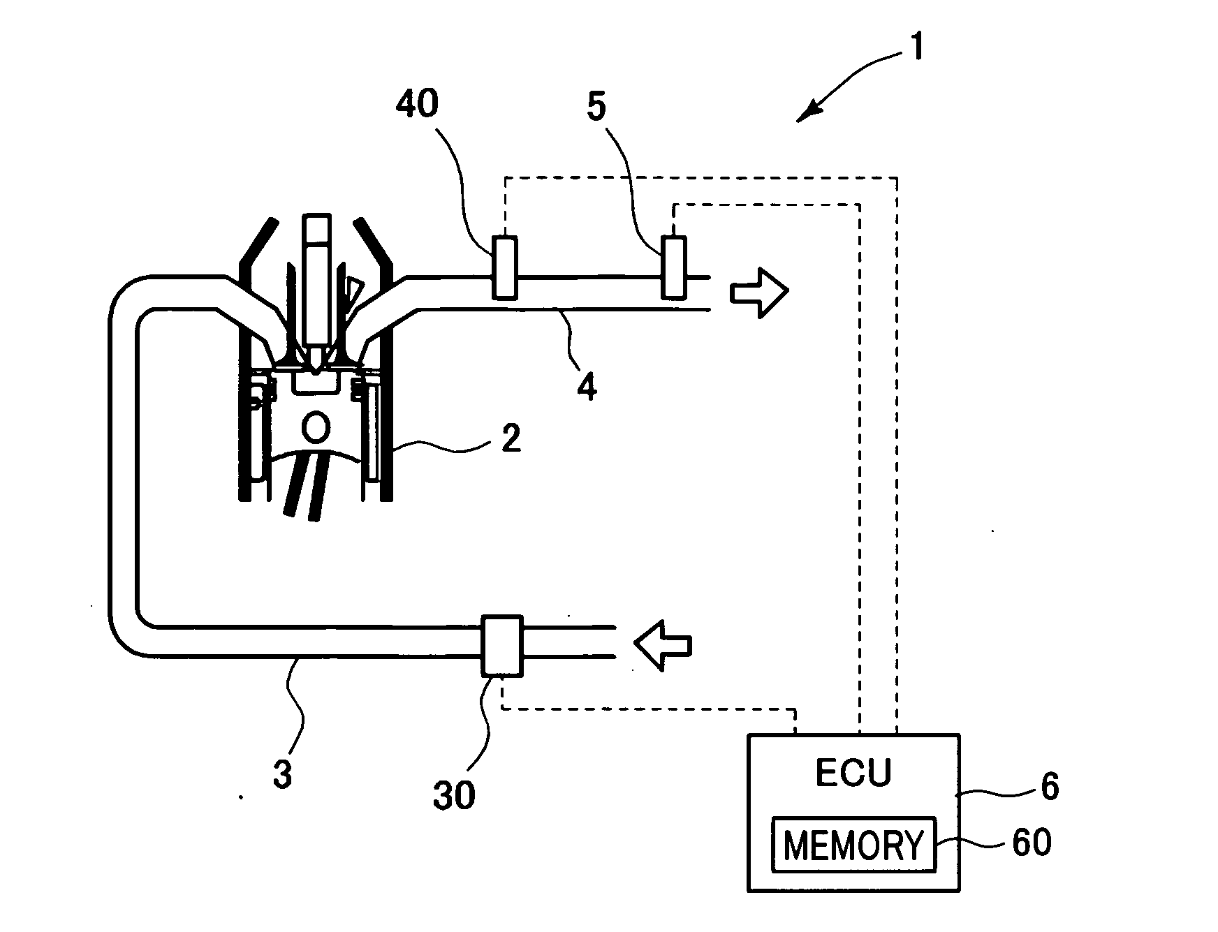
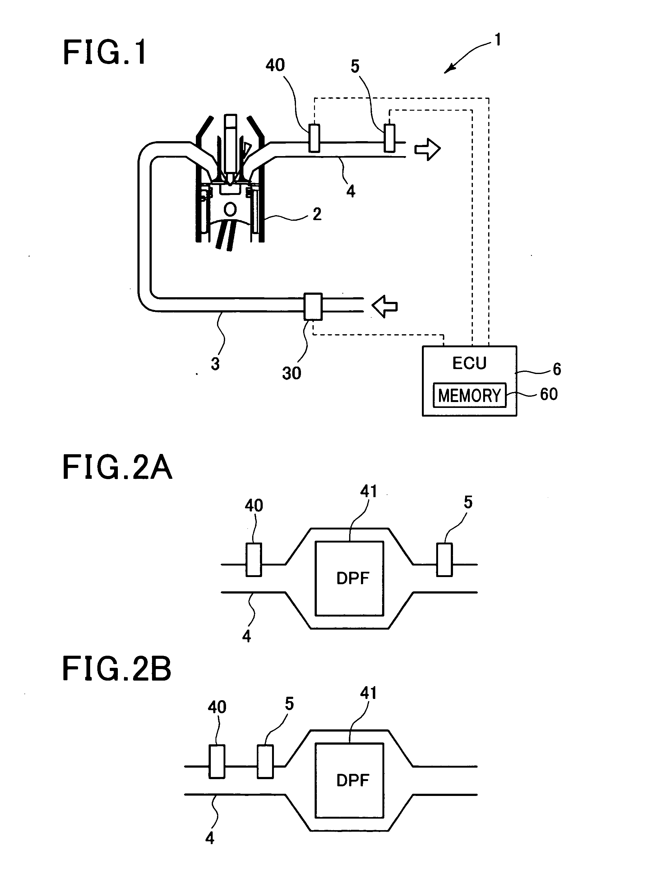
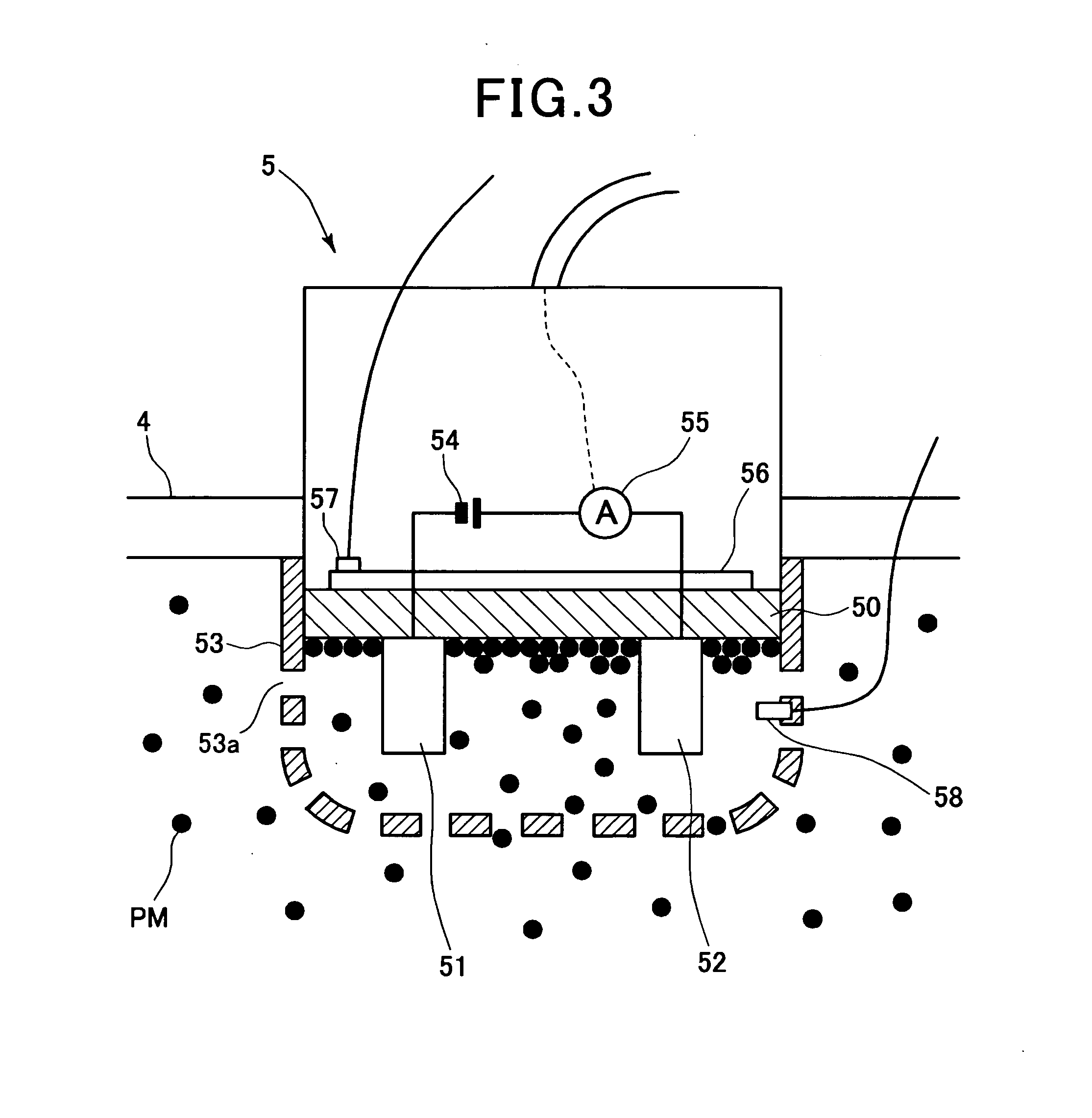
[0052]Referring first to FIGS. 1 to 4, 7 and 10 to 13, a first embodiment of the present invention is described. FIG. 1 is a schematic diagram illustrating a detection system 1 that configures a detection apparatus according to the first embodiment. The detection system 1 is used for detecting the amount of particulate matter (PM) flowing through an exhaust pipe (exhaust path) 4 (hereinafter this amount is also referred to as “PM amount”) of a diesel engine 2 (engine) that is an internal combustion engine. The detection system 1 also includes an intake pipe 3 that supplies intake gas (air) to the engine 2. The intake pipe 3 (intake path) is provided with an air flow meter 30 that detects an intake volume (e.g., mass flow rate per unit time). The exhaust pipe 4 of the engine 2 is provided with an exhaust temperature sensor 40 and a PM sensor 5.
[0053]The exhaust temperature sensor 40 detects the temperature of an exhaust gas (hereinafter also referred to as “exhaust temperature”). The...
second embodiment
[0079]Referring now to FIGS. 5 and 8, hereinafter is described a second embodiment of the present invention. In the first embodiment described above, a PM flow amount in the exhaust pipe 4 has been corrected to eliminate the influence of thermal migration. In the second embodiment, a PM flow amount is corrected to eliminate the influence associated with exhaust flow speed, as well as the influence of thermal migration. The system configuration shown in FIGS. 1 to 3 may be used in the second embodiment.
[0080]FIG. 5 is a flow diagram illustrating a process performed by a detection apparatus according to the second embodiment. It should be appreciated that, in the second and the subsequent embodiments, the processing steps and the components identical with or similar to those of the first embodiment are given the same reference numerals for the sake of omitting unnecessary explanation.
[0081]In the process shown in FIG. 5, steps S50 and S70 are performed in addition to the steps of the ...
third embodiment
[0085]Referring to FIGS. 6 and 9, hereinafter is described a third embodiment of the present invention. In the third embodiment, a PM detection value is corrected to eliminate the influence of separation of the PM deposited on the sensing element 50, as well as the influence of thermal migration and the influence associated with exhaust flow speed. The system configuration shown in FIGS. 1 to 3 may be used in the present embodiment as well. FIG. 6 is a flow diagram illustrating a process performed by a detection apparatus according to the third embodiment. In the process shown in FIG. 6, steps S110 and S120 are performed in addition to the steps performed in the second embodiment. At step S110, the ECU 6 calculates a correction coefficient for a PM detection value (hereinafter also referred to as “coefficient 3”). The correction coefficient 3 is used for eliminating the influence of separation of the PM that has been accumulated on the surface of the sensing element 50 due to the in...
PUM
 Abstract
Description
Claims
Application Information
 - R&D
- Intellectual Property
- Life Sciences
- Materials
- Tech Scout
- Unparalleled Data Quality
- Higher Quality Content
- 60% Fewer Hallucinations
Browse by: Latest US Patents, China's latest patents, Technical Efficacy Thesaurus, Application Domain, Technology Topic, Popular Technical Reports.
© 2025 PatSnap. All rights reserved.Legal|Privacy policy|Modern Slavery Act Transparency Statement|Sitemap|About US| Contact US: help@patsnap.com


