Unlock instant, AI-driven research and patent intelligence for your innovation.

Medical image display apparatus, method and program

a medical image and display apparatus technology, applied in the field of medical image display apparatus, method and program, can solve the problems of inability to recognize the function of each region at a glance, difficulty in observation of morphological information, and low diagnosis efficiency, so as to achieve efficient recognition

Inactive Publication Date: 2012-07-26
FUJIFILM CORP
View PDF2 Cites 4 Cited by
  • Summary
  • Abstract
  • Description
  • Claims
  • Application Information

AI Technical Summary

Benefits of technology

The present invention provides a medical image display apparatus, method, and program that can efficiently display both morphological information and function information about a subject. The apparatus, method, and program allow for the easy recognition of areas of interest in a subject and the avoidance of difficulty in observing areas near the base line of an image. The display control means can adjust the distance between two divided images based on user input, making it easier for users to observe both morphology information and functional information. The apparatus, method, and program also allow for the rotation display of a CPR image with a functional image, which can be useful for quickly identifying the condition of a subject. Overall, the invention improves the efficiency and accuracy of medical image diagnosis.

Problems solved by technology

However, when the functional image and the morphological image are simply placed one on the other as disclosed in Patent Document 1, the function of each region of a subject may be recognized, but there is a problem that the efficacy of diagnosis becomes lower because the morphology of the subject is hard to recognize.
For example, when a SPECT image or the like is displayed on a CPR image of a blood vessel or the like obtained from a morphological image, such as a CT image, if the SPECT image or the like is simply displayed in such a manner to be placed directly on the CPR image, observation of morphology information, such as a stenosis condition and a plaque site of a blood vessel, becomes difficult because the images are placed one on the other.
Meanwhile, even if the functional image and the morphological image are separately displayed, there is a problem that the function of each region is not recognizable at a glance.

Method used


Image

  • Medical image display apparatus, method and program
  • Medical image display apparatus, method and program
  • Medical image display apparatus, method and program

Examples


Embodiment Construction

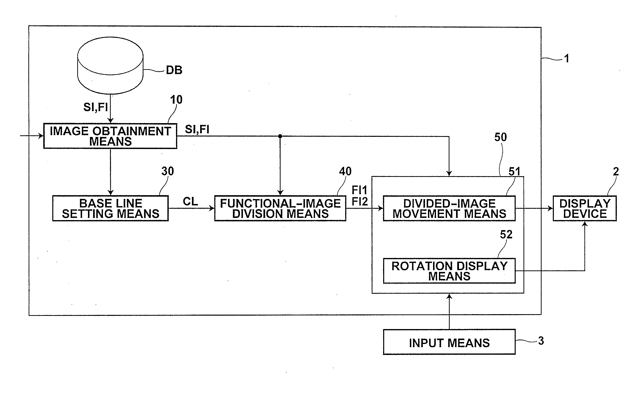
[0039]Hereinafter, embodiments of a medical image display apparatus of the present invention will be described in detail with reference to drawings. FIG. 1 is a schematic diagram illustrating the configuration of a medical image display apparatus 1 of the present invention. The configuration of the medical image display apparatus 1, as illustrated in FIG. 1, is realized by causing a computer to execute a medical image display program that has been read in an auxiliary storage device. At this time, the medical image display program is recorded in a recording medium, such as a CD-ROM, or distributed through a network, such as the Internet, and installed in the computer.

[0040]The medical image display apparatus 1 illustrated in FIG. 1 includes an image obtainment means 10, a base line setting means 30, an image division means 40, and a display control means 50. The image obtainment means 10 obtains first image SI and second image FI of subject S that have been generated based on volume...


PUM


Abstract

A medical image display apparatus includes an image obtainment unit configured to obtain a first image and a second image of a subject generated based on volume data, a base line setting unit configured to set a base line in the first image obtained by the image obtainment unit, an image division unit configured to divide, based on the base line that has been set in the first image by the base line setting unit, the second image into two divided images, and a display control unit configured to display the two divided images, which have been divided by the image division unit, on the first image at a display device in such a manner that the two divided images are away from the base line by a predetermined distance.

Description

BACKGROUND OF THE INVENTION[0001]1. Field of the Invention[0002]The present invention relates to a medical image display apparatus, method and program for displaying three-dimensional volume data and a functional image of a subject.[0003]2. Description of the Related Art[0004]Conventionally, a medical image display apparatus having a mode for observing the inner wall of a lumen of a subject as if seeing it from the inside of the lumen has been known. In this mode, an image of a three-dimensional structure is obtained by volume rendering based on three-dimensional digital data of an object obtained by CT or the like, and an image resembling an endoscopic image is generated based on the three-dimensional volume data to observe a lesion in a tubular organ, such as a blood vessel, intestines, bronchi and an artery, of the subject. Further, as three-dimensional image processing, MIP (Maximum Intensity Projection) processing, MinIP (Minimum Intensity Projection) processing, MPR (Multi Pla...

Claims


Application Information

Patent Timeline
Patent Type & Authority Applications(United States)
IPC IPC(8): G06T15/00
CPCG06T15/08G06T19/00A61B6/504A61B6/463G06T2215/06
Inventor HIRANO, MASAHARUSAKURAGI, FUTOSHIMASUMOTO, JUN
Owner FUJIFILM CORP