Tungsten oxide coated x-ray tube frame and anode assembly

a technology of tungsten oxide coating and x-ray tube, which is applied in the manufacture of x-ray tubes, electrode systems, electric discharge tubes/lamps, etc., can solve the problems of reducing the operating life/or the performance and operating efficiency of the tube, reducing the cooling of the anode assembly and other components, and reducing the cooling efficiency of the x-ray tube. , to achieve the effect of improving the cooling efficiency of th

Active Publication Date: 2012-07-26
GENERAL ELECTRIC CO
View PDF5 Cites 6 Cited by
  • Summary
  • Abstract
  • Description
  • Claims
  • Application Information

AI Technical Summary

Benefits of technology

[0012]The present invention overcomes the aforementioned problems by providing a method and apparatus for providing an x-ray tube having a coated x-ray tube frame inner surface and a coated anode assembly. The coating applied to the x-ray tube frame inner surface and anode assembly improves the emissivity of those surfaces, which improves the radiative heat transfer from a high temperature source (i.e., anode assembly) to a low temperature sink (i.e., x-ray tube frame).

Problems solved by technology

Over time, this heat can damage the anode, the anode assembly, and / or other tube components, and can reduce the operating life of the x-ray tube and / or the performance and operating efficiency of the tube.
While the rotating nature of the anode reduces the amount of heat present at the focal spot on the focal track, a large amount of heat is still present within the anode, the anode drive assembly, and other components within the evacuated housing.
This outer housing adds cost and complexity to the x-ray generating device, and can reduce its long term reliability.
While such emissivity values may be adequate and provide enough cooling to operate the x-ray tube, such values do not provide for optimal performance of the x-ray tube.
This adds cost and manufacturing complexity to the device, increases its overall size, and may not be desirable from an environmental and safety standpoint.

Method used


Image

  • Tungsten oxide coated x-ray tube frame and anode assembly
  • Tungsten oxide coated x-ray tube frame and anode assembly
  • Tungsten oxide coated x-ray tube frame and anode assembly

Examples


Embodiment Construction

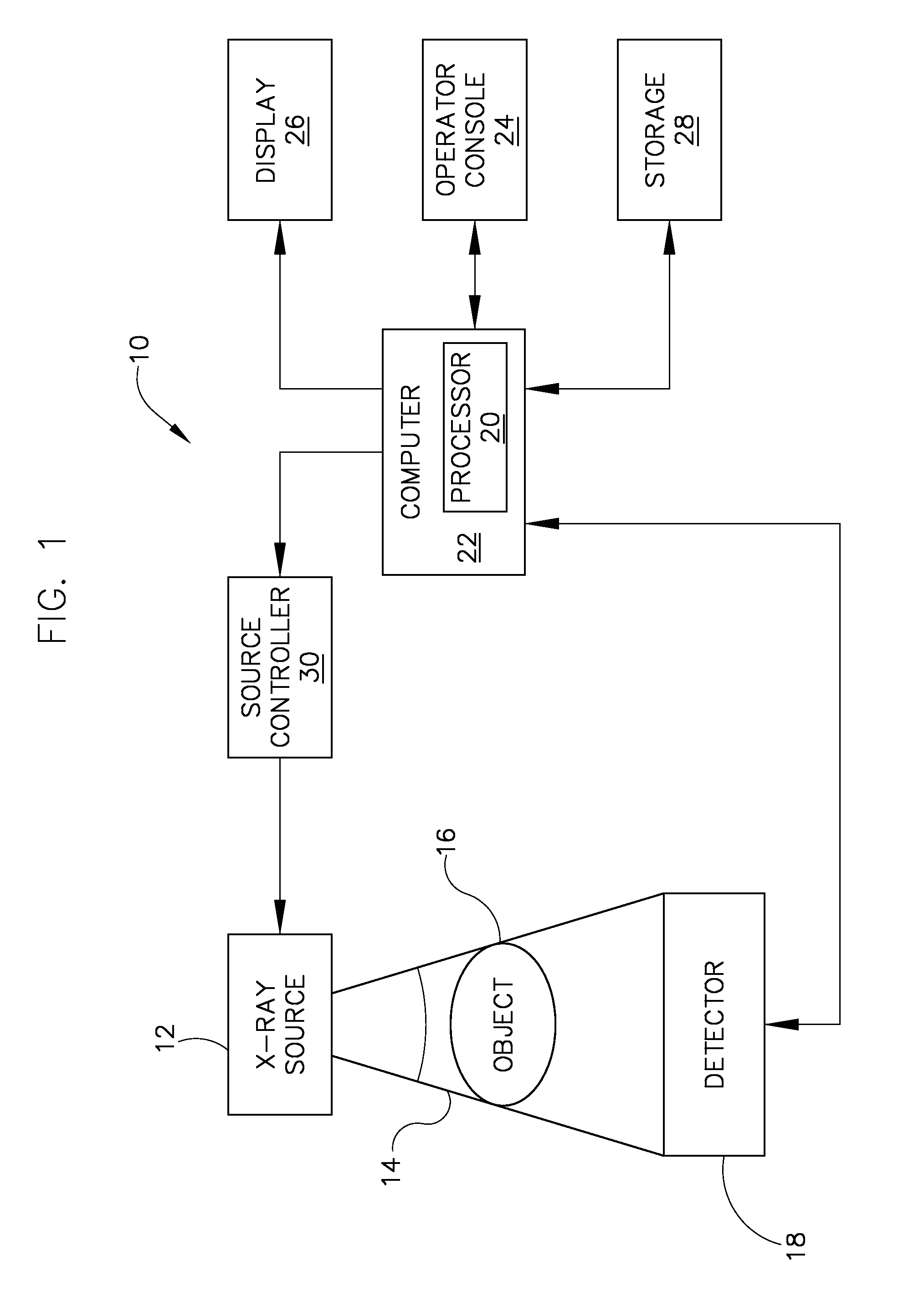
[0022]FIG. 1 is a block diagram of an embodiment of an imaging system 10 designed both to acquire original image data and to process the image data for display and / or analysis in accordance with the present invention. It will be appreciated by those skilled in the art that the present invention is applicable to numerous medical imaging systems implementing an x-ray tube, such as x-ray or mammography systems. Other imaging systems such as computed tomography systems and digital radiography systems, which acquire image three dimensional data for a volume, also benefit from the present invention. The following discussion of x-ray system 10 is merely an example of one such implementation and is not intended to be limiting in terms of modality.

[0023]As shown in FIG. 1, x-ray system 10 includes an x-ray source 12 configured to project a beam of x-rays 14 through an object 16. Object 16 may include a human subject, pieces of baggage, or other objects desired to be scanned. X-ray source 12 ...


PUM


Abstract

An x-ray tube having a coated x-ray tube frame inner surface and a coated anode assembly is provided. The x-ray tube includes an x-ray tube frame in which an anode assembly is disposed therein. A cathode assembly is also disposed within the x-ray tube frame that emits an electron beam to strike a target surface of the anode assembly and form x-rays. A plasma-sprayed tungsten oxide coating is formed on an inner surface of the x-ray tube frame and on the anode assembly to dissipate heat created by the electron beam.

Description

CROSS-REFERENCE TO RELATED APPLICATION[0001]The present application is a continuation-in-part of and claims priority to U.S. patent application Ser. No. 11 / 846,036 filed Aug. 28, 2007, the disclosure of which is incorporated herein.BACKGROUND OF THE INVENTION[0002]The present invention relates generally to x-ray imaging systems. More particularly, the present invention relates to systems and methods of improving heat transfer and lowering peak temperatures within an x-ray imaging tube.[0003]Traditional x-ray imaging systems include an x-ray source and a detector array. X-rays are generated by the x-ray source, pass through an object, and are detected by the detector array. Electrical signals generated by the detector array are conditioned to reconstruct an x-ray image of the object.[0004]In general, an x-ray generating device is formed with a vacuum housing that encloses an anode assembly and a cathode assembly. The cathode assembly includes an electron emitting filament that is cap...

Claims


Application Information

Patent Timeline
Patent Type & Authority Applications(United States)
IPC IPC(8): H01J35/10H01J9/00H01J35/02
CPCH01J35/105H01J35/12H01J35/16H01J2235/1233H01J2235/1216H01J2235/1229H01J2235/1204H01J35/10H01J35/108H05G1/025
Inventor SUBRAYA, MADHUSUDHANA T.
Owner GENERAL ELECTRIC CO
Why Eureka
Try Eureka