
Inferential load tracking

a load tracking and inferential technology, applied in the direction of vehicle position/course/altitude control, process and machine control, instruments, etc., can solve the problems of reducing driver and vehicle productivity, unsatisfactory solutions, and difficulty in determining asset or unit load location, so as to improve operational efficiency

Inactive Publication Date: 2012-07-26
TOTALTRAX
View PDF11 Cites 161 Cited by
  • Summary
  • Abstract
  • Description
  • Claims
  • Application Information

AI Technical Summary

Benefits of technology

[0036]The system described above removes operator involvement from the data collection task and improves operational efficiency as well as operator safety as loads are moved through a facility.

Problems solved by technology

The ability to automatically determine and record the identity, position, elevation, and rotational orientation of assets and / or unit loads within a defined coordinate space, without human interaction, is a practical problem that has seen many imperfect solutions.
Determining asset or unit load location has been an equally challenging problem, especially in facilities where goods move quickly from point to point, or where human interaction is relied upon to determine the asset's or unit load's location or storage position.
Tracking the movement of assets in a storage facility presents a number of additional problems.
The act of manually collecting the load tracking data creates several problems including, for example:1) Driver and vehicle productivity are reduced.
The label-reading task takes time away from the driver's primary task of moving the materials.2) Data errors can occur.
These data errors can result in lost inventory, inefficient operations, and operational disruptions.3) Driver safety is threatened.
Forklift drivers work in a dangerous environment.
The driver is exposed to potential injury when dismounted or leaning outside the protective cage.
In addition to the difficulties introduced by the manual data collection task, an overriding concern is that item identification tags, labels, or other markings can be degraded during shipping and storage, and may become unusable.
For example, paper labels with machine-readable barcode identifiers can be torn or defaced, rendering the barcode unreadable.
Printing can become wet and smeared, text can be misinterpreted, and labels can be torn off, rendering an item unidentifiable.
For indoor navigation, however, GPS signals can be attenuated, reflected, blocked, or absorbed by building structure or contents, rendering GPS unreliable for indoor use.
For example, object orientation is difficult to determine using radio waves.
A number of radio-based systems have been developed using spread spectrum RF technology, signal intensity triangulation, and Radio Frequency Identification (RFID) transponders, but all such systems are subject to radio wave propagation issues and lack orientation sensing.
An important shortcoming of the technology is that object orientation cannot be determined if an object is stationary.
Ultrasonic methods can work well in unobstructed indoor areas, although sound waves are subject to reflections and attenuation problems much like radio waves.
Similar to the GPS system in architecture, it lacks accurate orientation determination.
Using this type of system in a bulk storage facility where goods may be stacked on the floor has presented a limitation for laser scanning systems, which rely on the targets to be placed horizontally about the building in order to be visible to the sensor.
Items stacked on the floor that rise above the laser's horizontal scan line can obstruct the laser beam, resulting in navigation system failure.
The close proximity of many items also creates the problem of discriminating from them only those items intended for the current load.
Existing methods / systems do not address the problem of an asset being transported by a conveying vehicle, then loaded onto an automated conveying device and then being retrieved at another location by a second conveying vehicle for subsequent transport.
The prior art also does not address the issue of tracking a load if its identity is unknown when the conveying vehicle approaches the load.

Method used


Image

  • Inferential load tracking
  • Inferential load tracking
  • Inferential load tracking

Examples


example

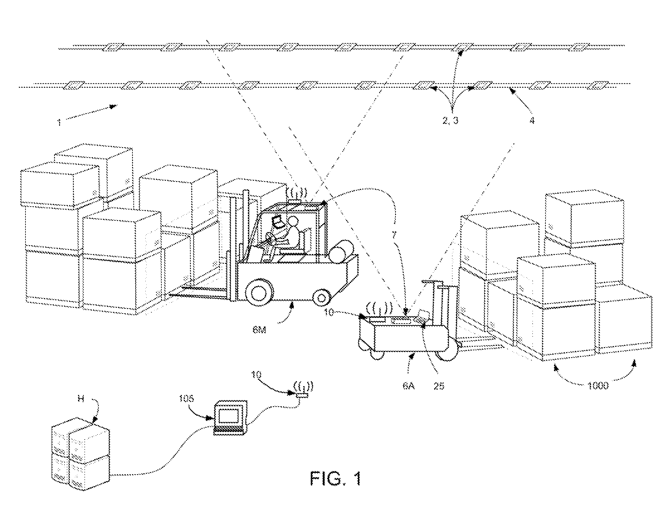
[0205]FIGS. 29 and 30 show examples of the Label Map and Load Map for the Example illustrated in FIGS. 31 and 32. FIGS. 31 and 32 illustrate a map of a warehouse during the transfer of a load from a first storage location to a second storage location using two conveying vehicles 106, 107. Two manned vehicles 106 and 107 are shown. A plurality of obstructions B1 through B11 (which may be storage racks or building structure) and an office area B12 are shown.

[0206]Preparatory to commencing warehouse operations a map of the coordinate space (i.e., the warehouse) is created to determine allowable travel routes for vehicles, locations of obstacles within the coordinate space, and practical names for storage locations. The map of the coordinate space is stored within the memory in the controller (computer 105 in the office area). One suitable way for creation of the map of the coordinate space is described in U.S. patent application Ser. No. 12 / 807,325.

[0207]In this example the system has ...


PUM


Abstract

Methods and apparatus for tracking the location of one or more unit loads in a coordinate space in a facility, comprising an integrated system that identifies a load by communicating with a host computer, determines the position of the load in the coordinate space, and stores the position and load identity in a Load Map. A mobile subsystem on each conveying vehicle identifies the location and orientation of that vehicle using a position / orientation sensor, confirms acquisition of the load, and communicates the information to a fixed-base subsystem when the load is deposited on an automated conveying device. A conveyor controller tracks the load as it is conveyed on the automated conveying device and identifies the load to a subsequent conveying vehicle based upon its position on the conveying device. Loads that are not initially identified are assigned a pseudo-identification for tracking until they can be positively identified.

Description

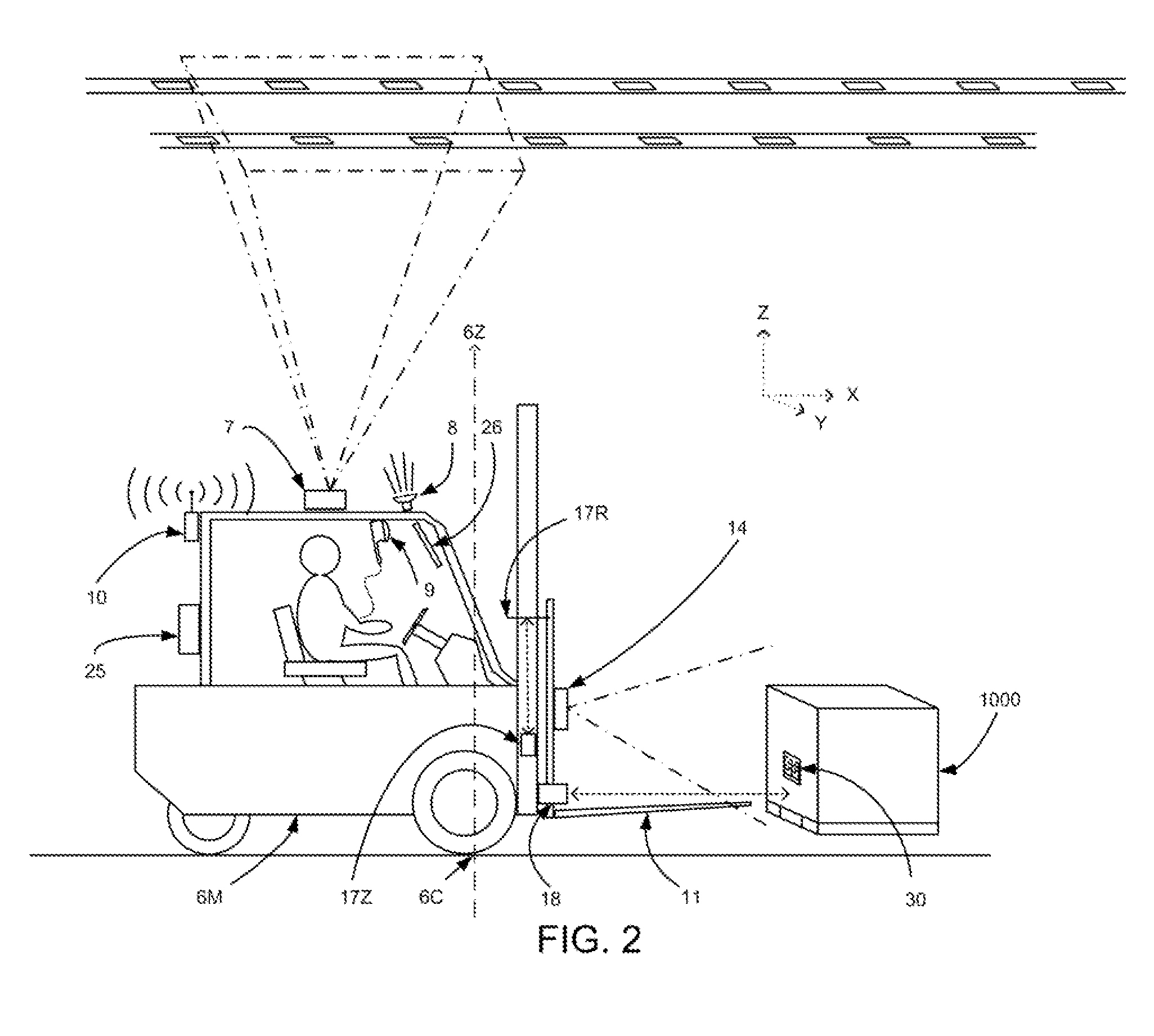
PRIORITY CLAIM[0001]This application claims the benefit of U.S. Provisional Patent Application Ser. No. 61 / 435,691, filed 24 Jan. 2011.TECHNOLOGY FIELD[0002]A method and apparatus for determining the location of one or more unit loads of freight in a coordinate space in a facility by reading identifying indicia to identify items, spatially discriminating the items from nearby ones, determining the position and orientation of items by determining the position and orientation of the conveying vehicles such as forklift trucks, and the position of the indicia relative to the conveying vehicle. The identity, location, and orientation of items are stored in a database in a computer memory that can be accessed by all conveying vehicles in the facility; thereby eliminating the necessity of rereading the identifying indicia each time an item is to be located for conveyance. Items may therefore be identified, located and tracked in “real” space of the facility and / or in “virtual” space of com...

Claims


Application Information

Patent Timeline
Patent Type & Authority Applications(United States)
IPC IPC(8): G06Q10/08G05D1/00
CPCG05D1/0088G05D2201/0216B66F9/24G05D1/0234B66F9/0755G06Q10/087G05D1/0274
Inventor ANDERSEN, SCOTT P.KUNZIG, ROBERT S.TAYLOR, ROBERT M.MAXWELL, LEONARD J.
Owner TOTALTRAX
Learn More