Electric power generation system

Active Publication Date: 2012-08-02
SUMITOMO ELECTRIC IND LTD
View PDF5 Cites 21 Cited by
  • Summary
  • Abstract
  • Description
  • Claims
  • Application Information

AI Technical Summary

Benefits of technology

[0029]The present electric power generation system has the following effects: (1) it utilizes wind power, and accordingly, it can generate electric power at night, and if it is provided with a heat accumulator, it can have the heat accumulator smaller in size than a solar thermal power generation system can; (2) it exploits the wind turbine's rotational energy to generate heat and uses the heat to generate electric power. This eliminates the necessity of providing an electric power storage system; and (3) it can dispense with a speed up gear, and thus be free of troubles caused by a gear box.

Problems solved by technology

Such a large-sized wind power generation system is huge and a heavy load, and accordingly, it is built on the sea for reasons of construction in many cases.

Method used


Image

  • Electric power generation system
  • Electric power generation system
  • Electric power generation system

Examples


first embodiment

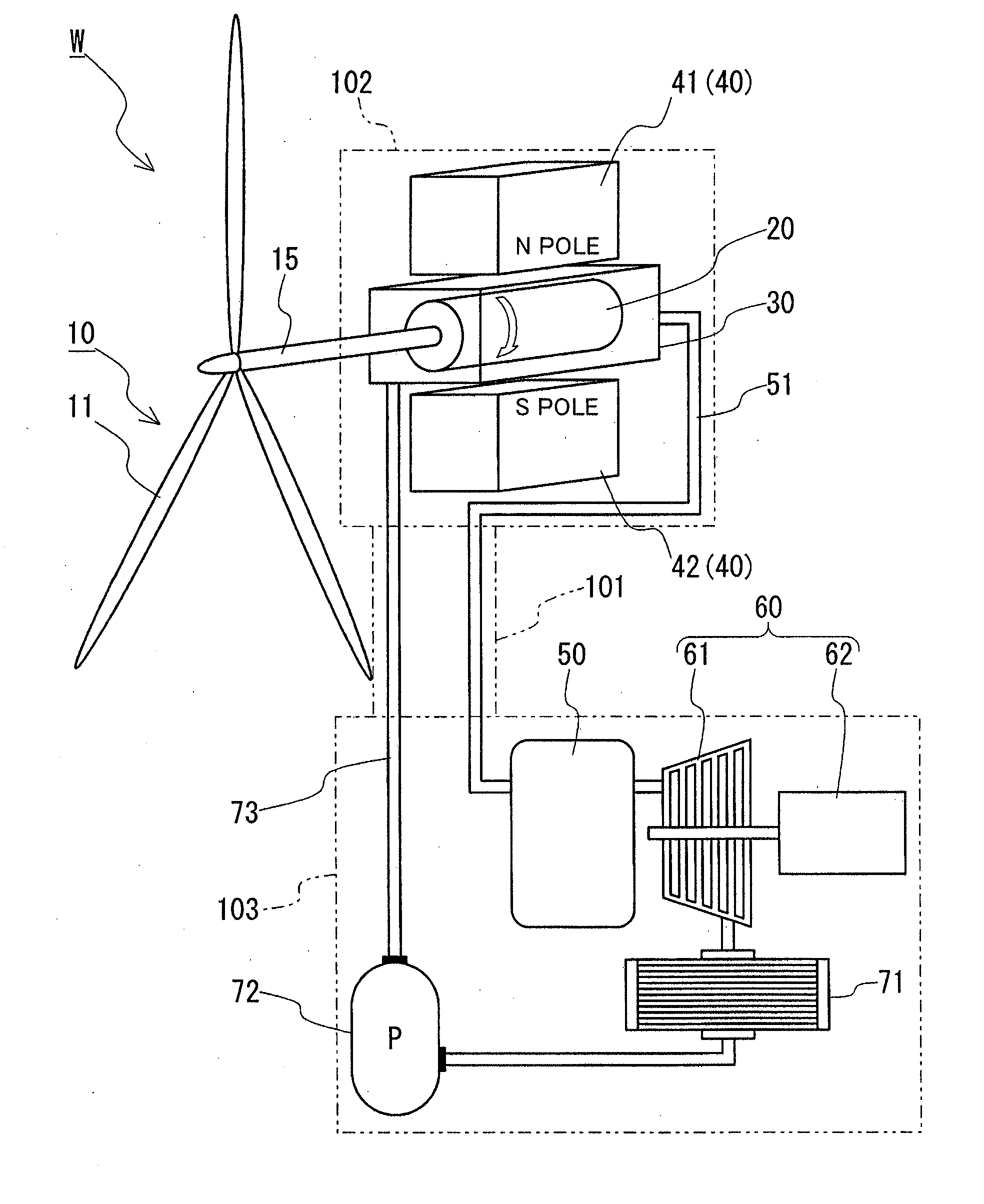
[0034]FIG. 1 shows an electric power generation system W including a wind turbine 10, a conductor 20, a heat transfer medium vessel 30, a magnetic field generator 40, a heat accumulator 50, and an electric power generation unit 60. Wind turbine 10 is attached to a nacelle 102 provided at an upper portion of a tower 101, and conductor 20, heat transfer medium vessel 30 and magnetic field generator 40 are housed in nacelle 102. Furthermore, heat accumulator 50 and electric power generation unit 60 are provided in a building 103 built at a lower portion (or a base) of tower 101. Electric power generation system W is configured, as will be described hereinafter more specifically.

[0035]Wind turbine 10 is structured with a horizontally extending rotary shaft 15 and three blades 11 attached to rotary shaft 15 radially. For a wind power generation system with an output exceeding 5 MW, it has a diameter of 120 m or larger and a rotational speed of approximately 10-20 rpm.

[0036]Conductor 20 i...


PUM


Abstract

An electric power generation system includes a wind turbine, a conductor rotating as the wind turbine rotates, a heat transfer medium vessel, a magnetic field generator, a heat accumulator, and an electric power generation unit. The magnetic field generator is operated to generate a magnetic field and therein the conductor is rotated and thus heated through induction, and the conductor's heat is transmitted to the water in the heat transfer medium vessel to generate steam which is in turn supplied to a steam turbine and thus drives an electric power generator to generate electric power.

Description

TECHNICAL FIELD[0001]The present invention relates to an electric power generation system which utilizes wind power to rotate a conductor and applies a magnetic field to the rotating conductor to heat the conductor through induction to heat a heat transfer medium and converts the heat transfer medium's heat into electrical energy to generate electric power.BACKGROUND ART[0002]In recent years, electric power generation systems utilizing recyclable energy, such as wind power and solar light, attract attention in view of greenhouse effect gas reduction.[0003]For example, Non-Patent Literature 1-3 describe technology relating to wind power generation. Wind power generation rotates a wind turbine by wind to drive an electric power generator to generate electric power. In other words, it converts wind energy into rotational energy and extracts it as electrical energy. A wind power generation system is generally structured such that a tower has an upper portion provided with a nacelle havi...

Claims


Application Information

Patent Timeline
IPC IPC(8): F03D1/00
CPCF03D9/006F03D9/02F05B2220/602F05B2220/702H05B6/108Y02E10/726Y02B10/30Y02B10/70Y02E10/721Y02E10/725H05B6/109H05B6/02F05B2220/301F03D9/14F03D9/18F03D9/22F03D15/20F03D80/82Y02E10/72Y02E60/16Y02E70/30Y02P70/50F01D15/10F03D80/80F01D13/02F01K3/186F03D1/00H02K7/1823
Inventor OKAZAKI, TORU
Owner SUMITOMO ELECTRIC IND LTD
Why Eureka
Try Eureka