Jittering frequency control circuit and method for a switching mode power supply

a frequency control circuit and power supply technology, applied in the direction of dc-dc conversion, power conversion systems, oscillation generators, etc., can solve the problems of increasing emi during frequency reduction mode, affecting the emi of switching mode power supply, and affecting the overall power consumption of the switch. achieve the effect of improving the emi of the switching mode power supply, and improving the emi of the switching mod

Active Publication Date: 2012-08-02
RICHTEK TECH
View PDF5 Cites 64 Cited by
  • Summary
  • Abstract
  • Description
  • Claims
  • Application Information

AI Technical Summary

Benefits of technology

[0010]A further objective of the present invention is to provide a jittering frequency control circuit and method for improving EMI of a switching mode power supply in a frequency reduction mode.
[0011]According to the present invention, a jittering frequency control circuit for a switching mode power supply includes an oscillator and a jittering frequency modulator. The oscillator provides a frequency jittered clock whose frequency determines the switching frequency of the switching mode power supply. The jittering frequency modulator generates a jittering frequency adjust signal according to an output feedback signal and a reference signal and thereby adjusts the range of the jittering frequency. Preferably, when the switching mode power supply enters a frequency reduction mode, the jittering frequency modulator adjusts at least one of the upper limit and the lower limit of the

Problems solved by technology

When a switching mode power supply is working at light load or in standby mode, the switching loss of its power switches accounts for a significant proportion of the overall power consumption.
Moreover, switching mode power supplies, though advantageously more compact than conventional linear power supplies, have another problem that electro-magnetic interference (EMI) caused by the switchin

Method used


Image

  • Jittering frequency control circuit and method for a switching mode power supply
  • Jittering frequency control circuit and method for a switching mode power supply
  • Jittering frequency control circuit and method for a switching mode power supply

Examples


first embodiment

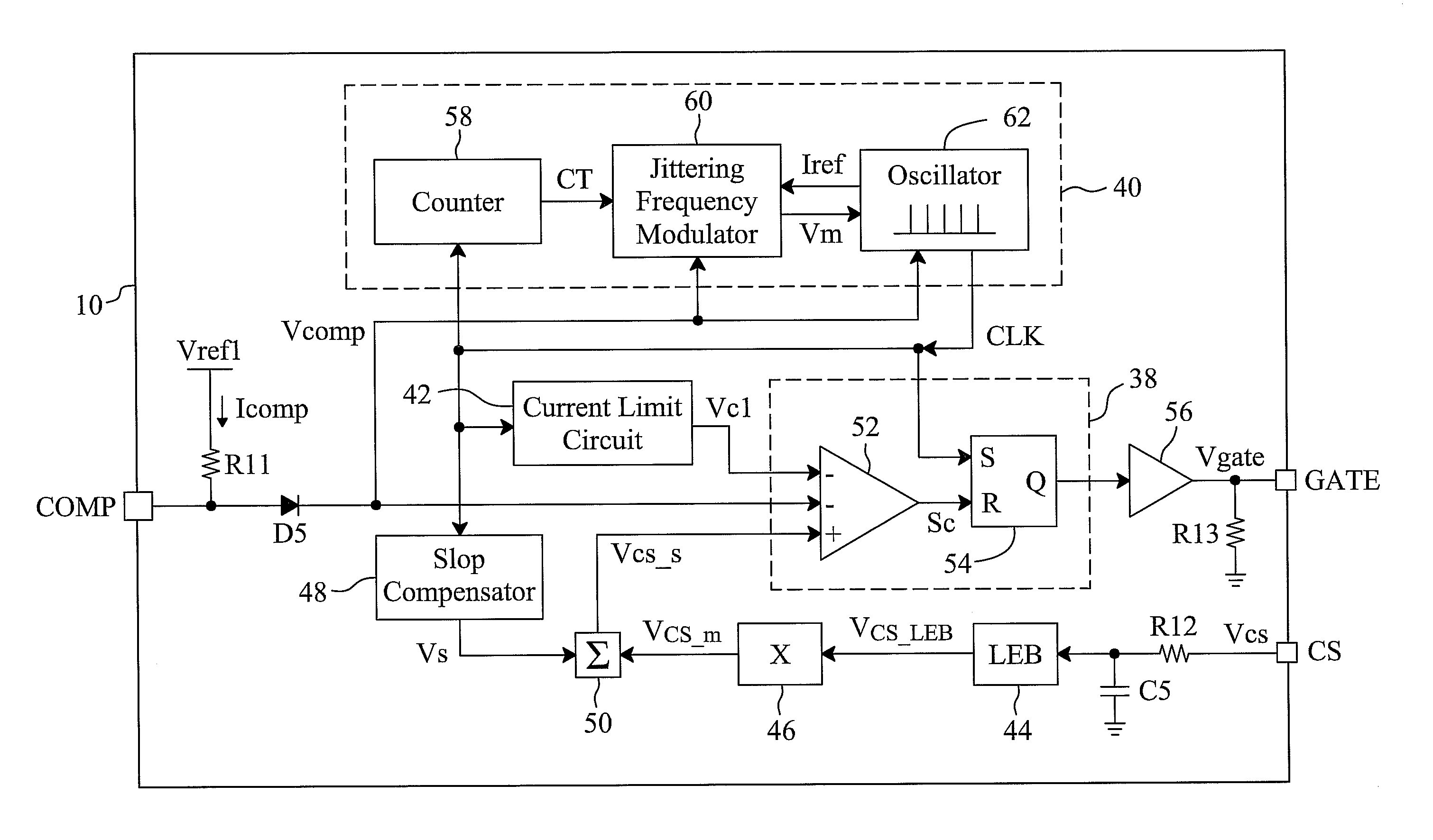
[0024]FIG. 6 is a circuit diagram of a first embodiment for the jittering frequency modulator 60 shown in FIG. 4. In this embodiment, the jittering frequency adjust signal Vm is a voltage provided by a capacitor Cm, the reference signal Iref is a current, a current mirror circuit 76 mirrors the current Iref to generate a charge current I1 and a discharge current I2, an AND gate 72 generates a signal S3 according to the count value CT and a signal S2, an AND gate 74 generates a signal S4 according to the count value CT and a signal S1, a switch SW1 is connected between the current mirror circuit 76 and the capacitor Cm and, in response to the signal S3, switches the charge current I1 to charge the capacitor Cm, a switch SW2 is connected between the current mirror circuit 76 and the capacitor Cm and, in response to the signal S4, switches the discharge current I2 to discharge the capacitor Cm, a comparator 70 compares the feedback voltage Vcomp with a threshold Vref2 to generate a com...

second embodiment

[0028]FIG. 7 is a circuit diagram of a second embodiment for the jittering frequency modulator 60 shown in FIG. 4. As in the circuit of FIG. 6, the comparator 70 compares the feedback voltage Vcomp with the threshold Vref2 to generate the comparison signal VFR. A current-to-voltage converter 96 has an input terminal to receive the reference current Iref. A current source 92 provides an adjust current IFR, and a switch 94 is connected between a current source 92 and the input terminal of the current-to-voltage converter 96 and is controlled by the comparison signal VFR. A voltage Vcv generated by the current-to-voltage converter 96 is converted by voltage-to-current converters 98-106 into currents I3-I7, respectively, a switch 108 is connected between an output terminal of a voltage-to-current converter 98 and an input terminal of the current-to-voltage converter 118, a switch 110 is connected between an output terminal of the voltage-to-current converter 100 and the input terminal o...


PUM


Abstract

A jittering frequency control circuit and method for a switching mode power supply enlarge the uttering frequency range of the switching frequency of the switching mode power supply when the switching mode power supplier enters a frequency reduction mode, to improve the electro-magnetic interference of the switching mode power supply operating with the frequency reduction mode.

Description

FIELD OF THE INVENTION[0001]The present invention is related generally to a switching mode power supply and, more particularly, to a jittering frequency control circuit and method for a switching mode power supply.BACKGROUND OF THE INVENTION[0002]Pulse width modulation (PWM) has been extensively applied to various electronic devices. For example, PWM controllers are used in switching mode power supplies to modulate duty cycles or switching frequencies of power switches and thereby modulate output voltages.[0003]Recently, due to energy shortages and the rising awareness of environmental protection, the energy saving feature of switching mode power supplies has drawn more and more attention. At the same time, laws and regulations were passed to impose stricter requirements on the power conversion efficiency of switching mode power supplies at light load and in standby mode. When a switching mode power supply is working at light load or in standby mode, the switching loss of its power ...

Claims


Application Information

Patent Timeline
IPC IPC(8): H03B19/00
CPCH02M3/33507H02M1/44
Inventor LIN, KUN-YUHUANG, PEI-LUN
Owner RICHTEK TECH
Why Eureka
Try Eureka