
Demodulation method and system for a low-power differential sensing capacitive touch panel

a capacitive touch panel, low-power technology, applied in transmission systems, instruments, computing, etc., can solve the problems of increasing power consumption, increasing the difficulty of detecting increasing the sensitivity of the touch panel, so as to reduce the affection of common noise, improve the accuracy of the touch coordinate, and improve the effect of sensitivity

Active Publication Date: 2012-08-02
ORISE TECH CO LTD
View PDF7 Cites 26 Cited by
  • Summary
  • Abstract
  • Description
  • Claims
  • Application Information

AI Technical Summary

Benefits of technology

[0014]The object of the present invention is to provide a demodulation method and system for a low-power differential-sensing capacitive touch panel for reducing the affection of common noises and obtaining the optimal SNR to further increase the accuracy on a touch coordinate, wherein, when there is no touch, an integral capacitor of a detection circuit is not charged or discharged to thereby avoid the additional power consumption and thus reduce the power consumption.

Problems solved by technology

which causes an additional power consumption.
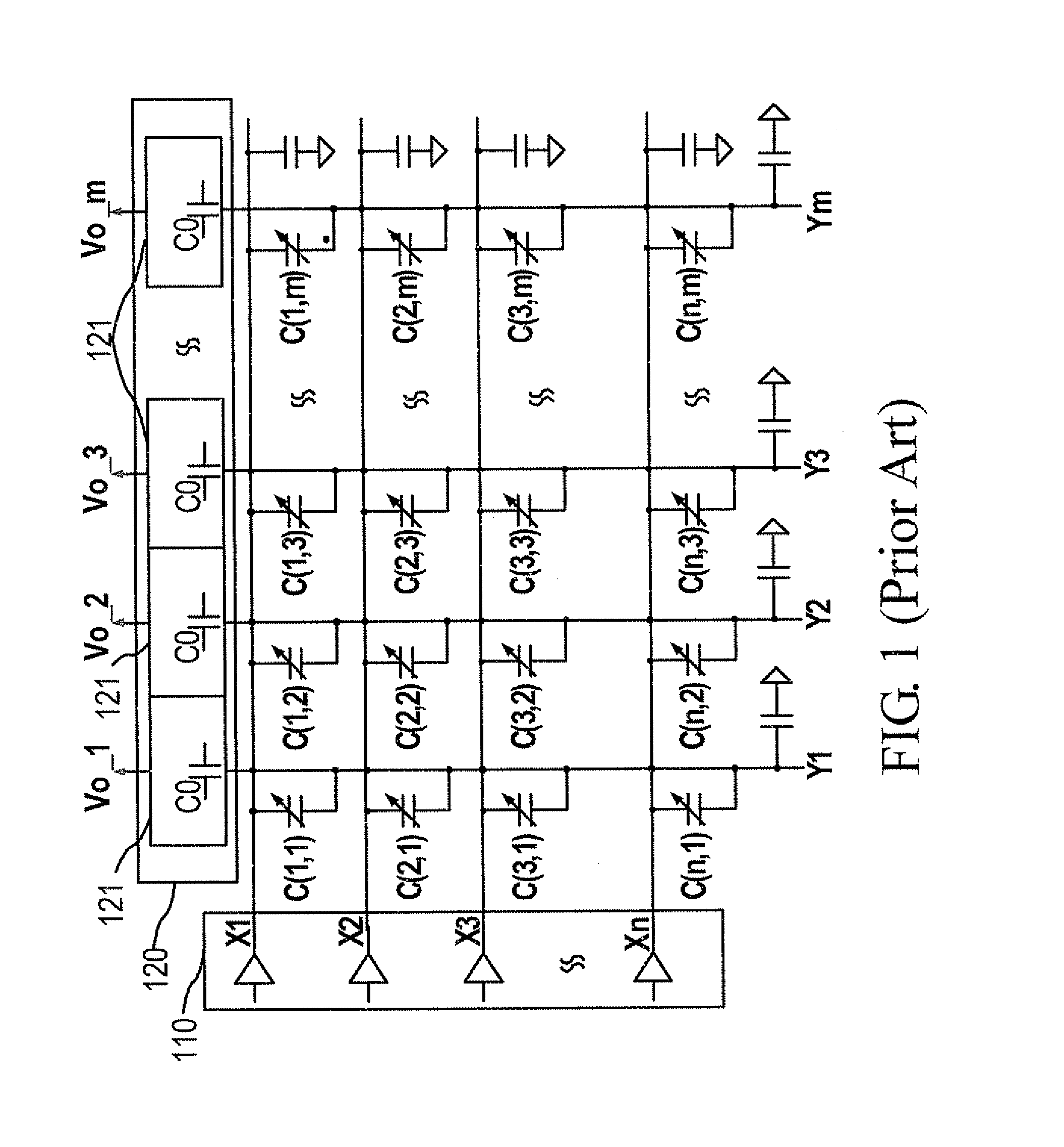
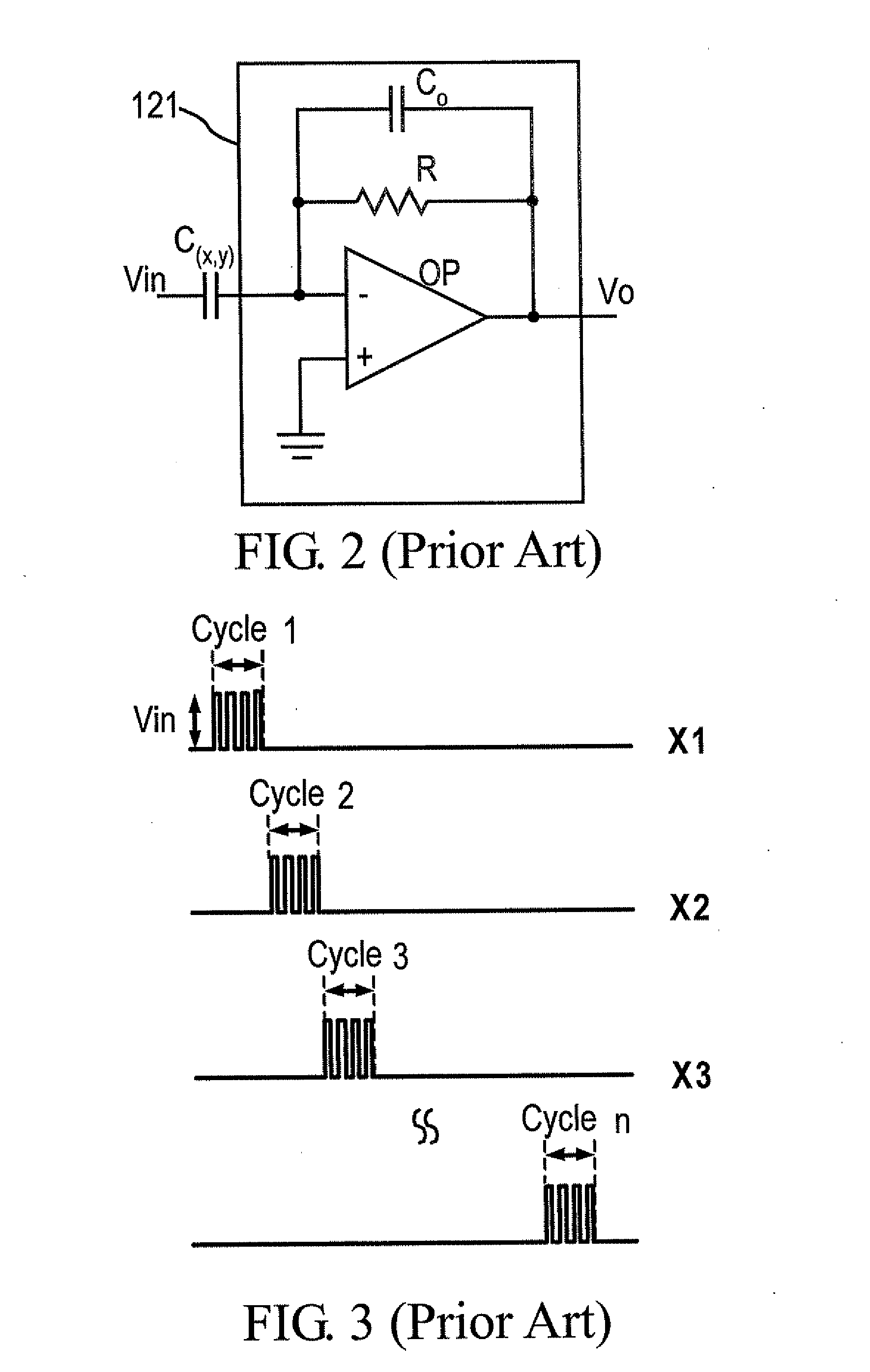
In addition, the common noises generated in the signal generator 110 and the conductor lines X1 to X3, such as a VCOM voltage generated in an LCD driver or a power noise generated in an LED driver, are detected and amplified by the sensing circuits 121, resulting in that the SNR (signal to noise ratio) is greatly decreased and the generated touch coordinate becomes unstable or even inaccurate.

Method used


Image

  • Demodulation method and system for a low-power differential sensing capacitive touch panel
  • Demodulation method and system for a low-power differential sensing capacitive touch panel
  • Demodulation method and system for a low-power differential sensing capacitive touch panel

Examples


Embodiment Construction

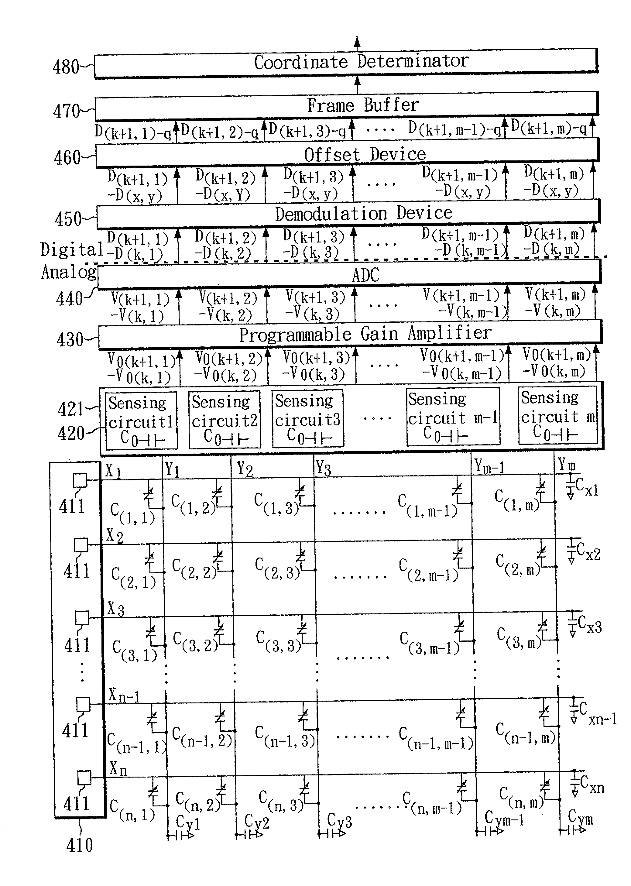
[0028]FIG. 4 is a block diagram of the demodulation system 400 for a low power differential sensing capacitive touch panel according to an embodiment of the invention. The capacitive touch panel has n first conductor lines X1 to Xn in a first direction and in second conductor lines Y1 to Ym in a second direction, where n, m are each an integer greater than one. A mutual capacitance C(x,y) is generated at each intersection between the first conductor lines X1 to Xn and the second conductor lines Y1 to Ym, wherein the first direction is vertical to the second direction. The demodulation system 400 includes a signal generator 410, a detection circuit 420, a programmable gain amplifier 430, an analog to digital converter (ADC) 440, a demodulation device 450, an offset device 460, a frame buffer 470, and a coordinate determinator 480.

[0029]The signal generator 410 has n voltage drivers 411 connected to the n first conductor lines X1 to Xn of the capacitive touch panel for driving the n f...


PUM


Abstract

In a demodulation system for a low-power differential-sensing capacitive touch panel, the capacitive touch panel has n first conductor lines in a first direction and m second conductor lines in a second direction, and a mutual capacitance is generated at each intersection of the n first conductor lines and the m second conductor lines. The demodulation system has a signal generator, a detection circuit, a programmable gain amplifier, an analog to digital converter. During a driving cycle, the signal generator generates a pair of differential driving signals to drive two of the first conductor lines in the first direction for eliminating common noises of the two first conductor lines and avoiding the common noises from being amplified by the programmable gain amplifier.

Description

CROSS REFERENCE TO RELATED APPLICATION[0001]This application claims the benefits of the Taiwan Patent Application Serial Number 100103888, filed on Feb. 1, 2011, the subject matter of which is incorporated herein by reference.BACKGROUND OF THE INVENTION[0002]1. Field of the Invention[0003]The present invention relates to the technical field of touch panels and, more particularly, to a demodulation method and system for a low-power differential sensing capacitive touch panel.[0004]2. Description of Related Art[0005]The modern consumer electronics are typically provided with touch panels for use as an input device. To meet with the requirements of light and compactness, a touch pad is usually combined with a display panel to form a touch panel for allowing a user to conveniently input data. Upon the sensing principle, touch pads are classified into four types including resistive type, capacitive type, surface acoustic wave type, or optics type.[0006]The principle of a touch panel is b...

Claims


Application Information

Patent Timeline
Patent Type & Authority Applications(United States)
IPC IPC(8): G06F3/044
CPCG06F3/044G06F3/0416G06F3/04166G06F3/0446
Inventor WANG, HSIN-HAOHUANG, YEN-LIN
Owner ORISE TECH CO LTD
Learn More