Touch screen sensor
a touch screen sensor and sensor technology, applied in the field of touch screen sensors, can solve the problems of placing limitations on the conductor design, and affecting the performance of the touch sensor, and achieve the effects of good optical quality, high optical quality, and visible light transmittan
- Summary
- Abstract
- Description
- Claims
- Application Information
AI Technical Summary
Benefits of technology
Problems solved by technology
Method used
Image
Examples
example 1
[0149]A micropattern of thin film gold according to the following description is deposited onto a thin sheet of colorless glass (approximately 1 millimeter in thickness). The micropattern 240 is depicted in FIG. 11 and FIG. 12. The thickness or height of the gold layer is about 100 nanometers. The micropattern 240 involves a series of horizontal (x-axis) mesh bars 241 comprising horizontal narrow traces 242, the traces 242 measuring approximately 2 micrometers in width. Four of these horizontal mesh traces 242 are in electrical communication with a larger feature contact pad 260. The mesh bars measure approximately 6 millimeters in width. Accordingly, with thirteen evenly spaced traces 244 traversing a width (y-axis) of 6 millimeters and thirteen evenly spaced traces 242 traversing a length (x-axis) of 6 millimeters, the pitch of the square grid of traces is 500 micrometers. As depicted in FIG. 12, certain traces have breaks 250, measuring approximately 25 micrometers (exaggerated i...
example 2
[0150]A micropattern of thin film gold according to the following description is deposited onto a thin sheet of colorless glass (approximately 1 millimeter in thickness). The micropattern 340 is depicted in FIG. 15. The thickness of the gold is about 100 nanometers. The micropattern 340 has transparent conductive regions in the form of a series of interdigitated wedges or triangles. Each wedge is comprised of a mesh made up of narrow metallic traces 342, 344, the traces 342, 344 (see FIG. 15a-FIG. 15c) measuring approximately 2 micrometers in width. The mesh wedges measure approximately 1 centimeter in width at their base and approximately six centimeters in length. The pitch of the square grid of traces 342, 344 is 500 micrometers. Within selected regions of the mesh (see FIG. 15a-FIG. 15b), within a wedge, breaks 350 measuring approximately 25 micrometers in length are placed intentionally to affect the local sheet resistance within the wedge, for current passing along its long ax...
example 3
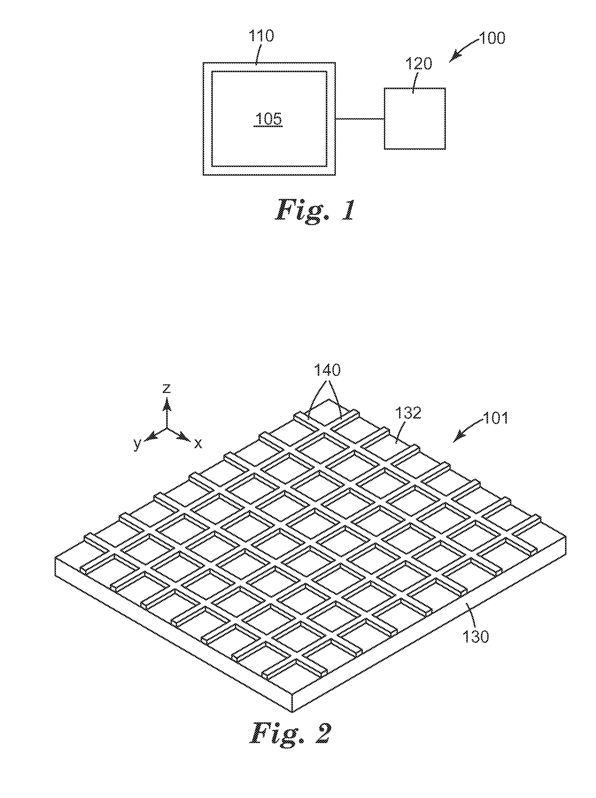
[0152]A transparent sensor element 400 for a touch screen sensor is illustrated in FIG. 17. The sensor element 400 includes two patterned conductor layers 410, 414, (e.g., an X axis layer and a Y axis layer) two optically clear adhesive layers 412, 416, and a base plate 418, laminated together and depicted as separated in FIG. 17 for clarity. Layers 410 and 414 include transparent conductive mesh bars where one layer is oriented in the x axis direction and the other layer is orientated in the y axis direction, with reference to FIG. 2. The base plate 418 is a sheet of glass measuring 6 centimeter by 6 centimeters in area and 1 millimeter in thickness. A suitable optically clear adhesive is Optically Clear Laminating Adhesive 8141 from 3M Company, St. Paul, Minn. For each of the X-layer and the Y-layer, a clear polymer film with a micropattern of metal is used. A micropattern of thin film gold according to the following description is deposited onto a thin sheet of PET. Suitable PET ...
PUM
 Abstract
Description
Claims
Application Information
 - R&D
- Intellectual Property
- Life Sciences
- Materials
- Tech Scout
- Unparalleled Data Quality
- Higher Quality Content
- 60% Fewer Hallucinations
Browse by: Latest US Patents, China's latest patents, Technical Efficacy Thesaurus, Application Domain, Technology Topic, Popular Technical Reports.
© 2025 PatSnap. All rights reserved.Legal|Privacy policy|Modern Slavery Act Transparency Statement|Sitemap|About US| Contact US: help@patsnap.com


