

Secondary battery including one-way exhaust member
- Summary
- Abstract
- Description
- Claims
- Application Information
AI Technical Summary
Benefits of technology
Problems solved by technology
Method used
Image

Examples
Embodiment Construction
[0056]Now, a preferred embodiment of the present invention will be described in detail with reference to the accompanying drawings. It should be noted, however, that the scope of the present invention is not limited by the illustrated embodiment.
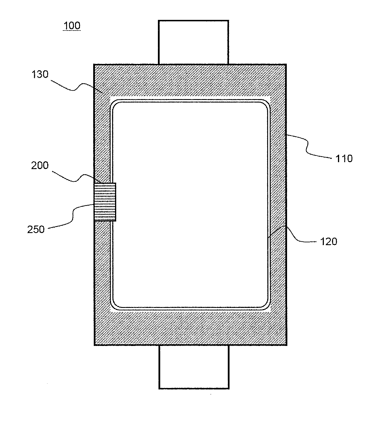
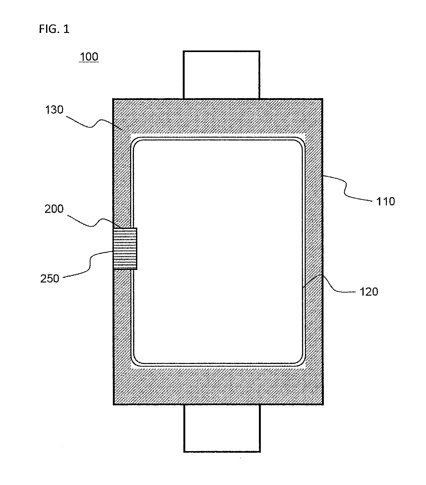
[0057]FIG. 1 is a plan view illustrating a pouch-shaped secondary battery according to a preferred embodiment of the present invention. The secondary battery of FIG. 1 is approximately identical to a conventional pouch-shaped secondary battery, which is being generally used, and therefore, only the characteristics of the present invention will be described hereinafter.
[0058]Referring to FIG. 1, the secondary battery 100 is constructed in a structure in which a sealed portion 130 is formed along the outer circumference of an electrode assembly receiving part 120 of a battery case 110, made of an aluminum laminate sheet, and a one-way exhaust member 200 is mounted at the sealing portion 130.
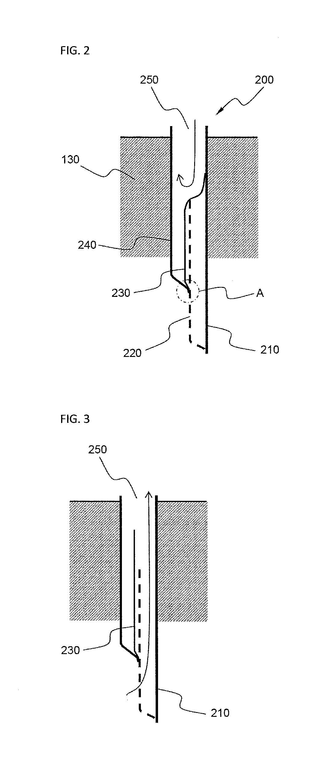
[0059]The one-way exhaust member 200 is constructed i...
PUM
 Abstract
Description
Claims
Application Information