
Electronic endoscope system

Inactive Publication Date: 2012-08-02
FUJIFILM CORP
View PDF29 Cites 26 Cited by
  • Summary
  • Abstract
  • Description
  • Claims
  • Application Information

AI Technical Summary

Benefits of technology

[0010]An object of the present invention is to improve the quality of a special image that captures weak light reflected or emitted from an internal body portion in response to application of special light.
[0022]According to the present invention, it is possible to obtain the clear special image.

Problems solved by technology

In capturing the weak fluorescence emitted from the internal body portion, even if the special light such as the excitation light emitted from the light source is filtered out and only the fluorescence is captured, a clear image suitable for the diagnosis is not necessarily obtained because the fluorescence itself is too weak.
The amplification of the signal by image processing, however, has a disadvantage that a noise component is also amplified proportionally.

Method used


Image

  • Electronic endoscope system
  • Electronic endoscope system
  • Electronic endoscope system

Examples


Embodiment Construction

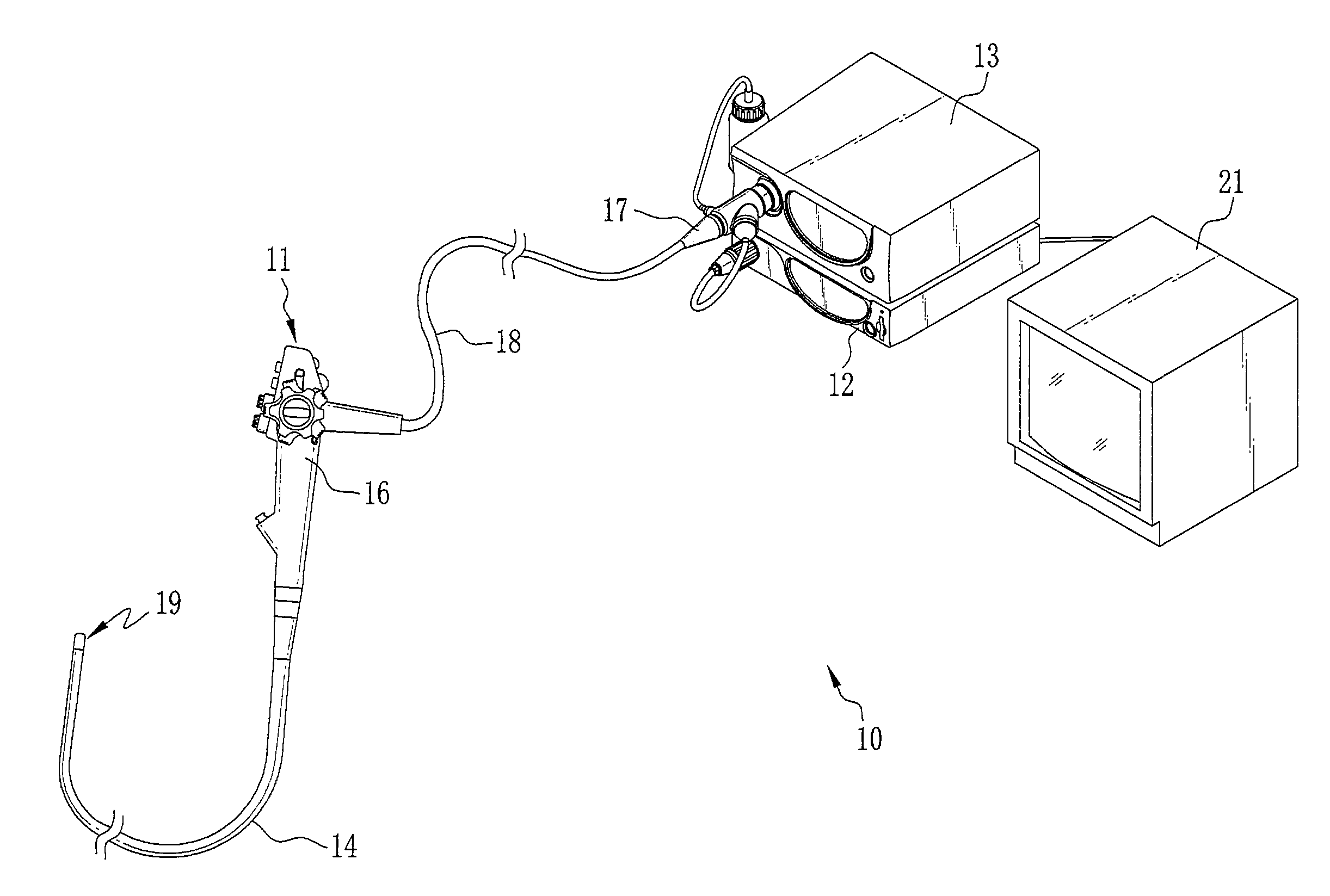
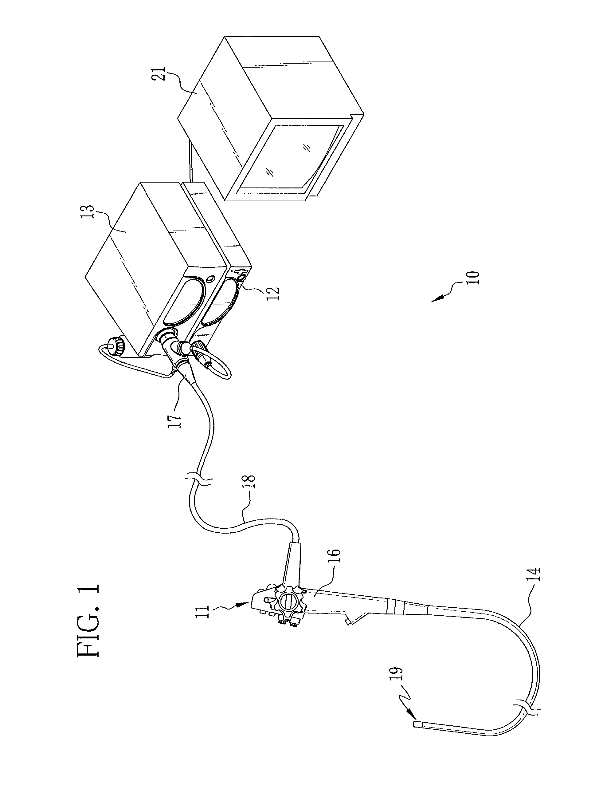
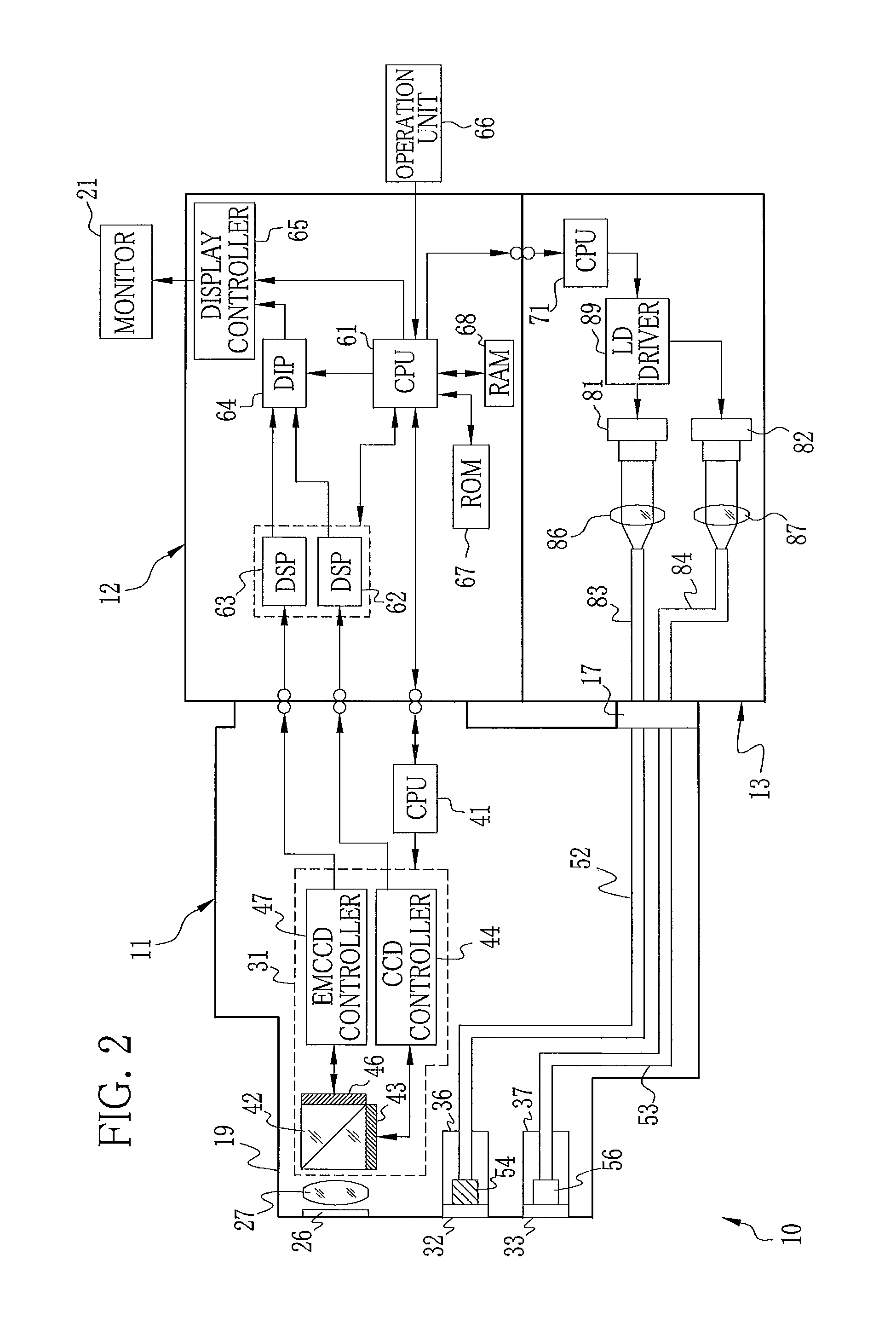
[0035]As shown in FIG. 1, an electronic endoscope system 10 is constituted of an electronic endoscope 11, a processor device 12, and a light source device 13. The electronic endoscope 11 includes a flexible insert section 14 to be introduced into a patient's body cavity, an operation section 16 coupled to a base end of the insert section 14, a connector 17 connected to the processor device 12 and the light source device 13, and a universal cord 18 for connecting the operation section 16 to the connector 17. The insert section 14 contains at its distal end portion 19 two types of image sensors, that is, a CCD 43 (see FIG. 2) for capturing an image under white light and an EMCCD (electron multiplying CCD) 46 (see FIG. 2) for capturing an image under special light.

[0036]On the operation section 16, there are provided operation members including an angle knob for flexibly bending the distal end portion 19 in a desired direction, an airing / watering button for ejecting air or water from t...


PUM


Abstract

In an electronic endoscope, an insert section has a beam splitter, a CCD, and an EMCCD at its distal end portion. When white light being normal light is applied to an internal body portion, the reflected white light is incident on the CCD through the beam splitter, and a normal image is produced. When the internal body portion is irradiated with special light being excitation light, weak autofluorescence is emitted from specific tissue of the internal body portion. The weak autofluorescence is incident on the EMCCD through the beam splitter. The EMCCD uses an avalanche multiplication effect in its electron multiplier. The EMCCD multiplies signal charge produced from the weak autofluorescence by the electron multiplier, and outputs a high level signal.

Description

BACKGROUND OF THE INVENTION[0001]1. Field of the Invention[0002]The present invention relates to an electronic endoscope system.[0003]2. Description of the Related Art[0004]Conventionally, electronic endoscope systems are widely used in medical diagnosis and treatment. The electronic endoscope system is constituted of an electronic endoscope having an insert section, a processor device and a light source device connected to the electronic endoscope, and the like.[0005]The electronic endoscope is provided with the insert section to be introduced into a patient's body cavity and an operation section for operating the insert section. In a distal end portion of the insert section, there are formed a lighting window through which illumination light is applied in the patient's body, and an imaging window through which the inside of the body is imaged. In the electronic endoscope, an image sensor captures through the imaging window an image of an internal body portion to be examined under ...

Claims


Application Information

Patent Timeline
IPC IPC(8): A61B1/04
CPCA61B1/00096A61B1/00186A61B1/043A61B1/045A61B1/0653A61B1/0638A61B1/00006A61B1/063A61B1/051A61B1/0655
Inventor MURAYAMA, JIN
Owner FUJIFILM CORP
Learn More