
Light emitting element, light emitting device, vehicular headlamp, illumination device, and method for producing the light emitting element

Active Publication Date: 2012-08-09
SHARP FUKUYAMA LASER CO LTD
View PDF8 Cites 28 Cited by
  • Summary
  • Abstract
  • Description
  • Claims
  • Application Information

AI Technical Summary

Benefits of technology

[0027]As described above, a light emitting element in accordance with an embodiment of the present invention includes a plurality of fluorescent material particles accumulated on a substrate to form a layer of the plurality of fluorescent material particles, each of the plurality of fluorescent material particles has a surface coated with a coating layer, and the coating layer forms an uneven shape of a surface of the light emitting element.
[0028]Further, a method for producing a light emitting element in accordance with an embodiment of the present invention is a method including the steps of: accumulating a plurality of fluorescent material particles on a substrate so as to form a layer of the plurality of fluorescent material particles; and coating each of surfaces of the plurality of fluorescent material particles with a coating layer such that the light emitting element has an uneven surface.
[0029]Therefore, the light emitting element in accordance with an embodiment of the present invention yields an effect of attaining a long life, and improving its durability and safety. A light emitting element production method of the present invention yields an effect of producing a light emitting element excellent in durability and safety with a long life.

Problems solved by technology

The techniques of these documents disclose using an electron gun, a fluorescent lamp, or an LED as an excitation light source, but do not disclose usage of a laser light source.
This permits human bodies to be highly likely to be in danger of being damaged, for example, human eyes are damaged by the laser light having a high coherency.

Method used


Image

  • Light emitting element, light emitting device, vehicular headlamp, illumination device, and method for producing the light emitting element
  • Light emitting element, light emitting device, vehicular headlamp, illumination device, and method for producing the light emitting element
  • Light emitting element, light emitting device, vehicular headlamp, illumination device, and method for producing the light emitting element

Examples


application examples

OF THE PRESENT INVENTION

[0123]A light emitting element (light emitting section 4) of the present invention is applicable not only to a vehicle headlamp but also to other illumination devices. For example, an illumination device of the present invention can be a downlight. The downlight is an illumination device attached to a ceiling of a structure such as a house or a vehicle. Instead, the illumination device of the present invention can be achieved as a headlamp for a moving object (e.g., a human, a ship, an airplane, a submersible, or a rocket) other than a vehicle. Further, the illumination device of the present invention can be achieved as a searchlight, a projector, or an interior illumination device (such as a stand light) other than the downlight.

example 1

[0124]The following description deals with concrete examples of the present invention with reference to FIG. 10. Note that members which are identical with members described in the foregoing embodiments have the same reference signs as those of the members described in the foregoing embodiments, and explanations of these are omitted here for the sake of simple explanation. Further, materials, shapes, and various values described below are merely examples, and the present invention is not limited to these.

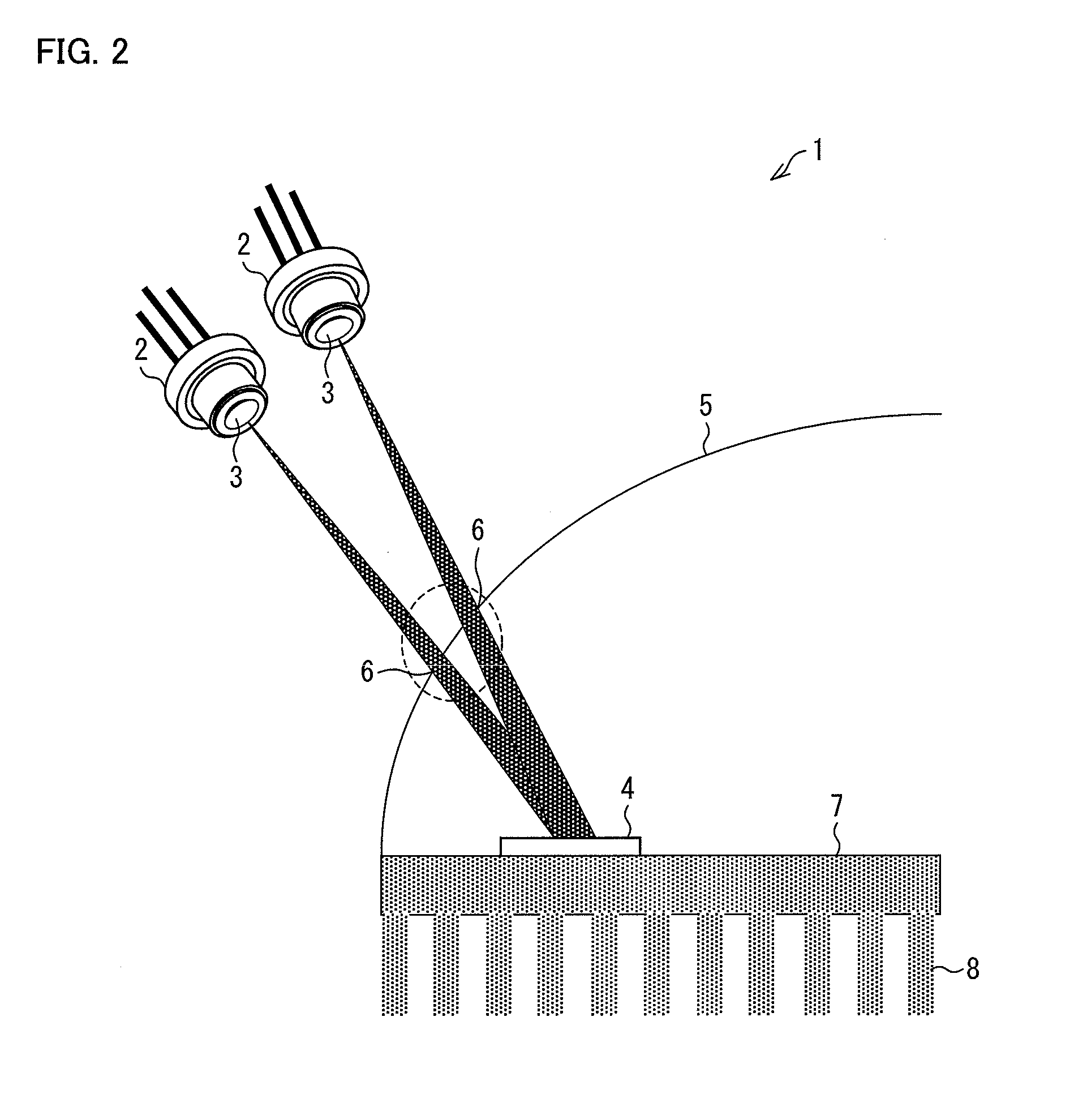
[0125]FIG. 10 is a view schematically illustrating a headlamp 20 in accordance with an example of the present invention. As shown in FIG. 10, the headlamp 20 includes a plurality of sets each including a laser element 2 and a condenser lens 11, a plurality of optical fibers (light guiding members) 12, a lens 13, a reflecting mirror 14, a light emitting section 4, a parabolic mirror 5, a metallic base 7, and fins 8.

[0126]Each of the condenser lenses 11 is a lens for causing a laser b...


PUM


Abstract

A light emitting section emits fluorescence upon receiving exciting light emitted from a laser element. The light emitting section includes a plurality of fluorescent material particles made from a single type of fluorescent material or several types of fluorescent materials, the plurality of fluorescent material particles being accumulated on a metal substrate to form a layer of the plurality of fluorescent material particles. Each of the plurality of fluorescent material particles has a surface coated with a coating layer. The coating layer forms an uneven shape of a surface of the light emitting section.

Description

[0001]This Nonprovisional application claims priority under 35 U.S.C. §119(a) on Patent Application N 2011-022021 filed in Japan on Feb. 3, 2011, the entire contents of which are hereby incorporated by reference.TECHNICAL FIELD[0002]The present invention relates to a light emitting element for emitting fluorescence in response to exciting light with which fluorescent material particles are irradiated, a method for producing the light emitting element, a light emitting device including the light emitting element, a vehicular headlamp, and an illumination device.BACKGROUND ART[0003]Recently, there has been eagerly studied a technique of emitting fluorescence by irradiating a fluorescent material layer with exciting light emitted from an excitation light source as which a semiconductor light emitting element such as a light emitting diode (LED) or a semiconductor laser (LD; Laser Diode) serves. Typical examples of an excitation light source of a light emitting device encompass (i) an e...

Claims


Application Information

Patent Timeline
IPC IPC(8): H01J1/62H01J9/00
CPCH01J29/20F21S48/328F21S48/1159F21S48/1131F21S41/125F21S41/16F21S41/176F21S45/47
Inventor MAEMURA, YOSUKETAKAHIRA, YOSHIYUKI
Owner SHARP FUKUYAMA LASER CO LTD
Learn More