Metal surface treatment method

a metal surface treatment and metal technology, applied in the direction of coatings, manufacturing tools, solventing apparatus, etc., can solve the problems of difficult surface treatment, cumbersome waste liquid treatment of various chemicals, and difficult plating process, and achieve the effect of simple system, simple and efficient manner, and efficient dissimilar metal film provision

Inactive Publication Date: 2009-12-24
KAZUO SAWAGUCHI +1
View PDF5 Cites 11 Cited by
  • Summary
  • Abstract
  • Description
  • Claims
  • Application Information

AI Technical Summary

Benefits of technology

[0057]Further, since the metal surface treatment method of the present invention is capable of obtaining a metal surface having a variety of properties such as lubricating ability, resistance to wear, resistance to corrosion, and releasability, this method can be applied to a metal surface of a product corresponding with an intended property as enumerated above.
[0058]Furthermore, the metal surface treatment method in accordance with a fifteenth aspect of the present invention carries the advantage that a variety of metals can be reliably bonded on the surface of various kinds of base metals in a simple, easy and efficient manner. This is possible because the surface treatment method of the present invention is so designed that the dissimilar metal particle being a metal particle different from the base metal is accelerated toward and impinged upon the surface of the base metal; the powdered metal layer is provided on the surface of the base metal via a binder becoming lost by the effect of the energy of the energy beam; the surface of the base metal provided with the powdered metal layer is irradiated with the energy beam of an electron beam or a laser beam; and the binder is lost for allowing the powdered metal layer and the base metal to be bonded together.
[0059]Particularly, in the surface treatment method in accordance with a fifteenth aspect of the present invention, the dissimilar metal particle is attached to the surface of the base metal by means the binder which becomes lost by the effect of the energy beam and the dissimilar metal particle is accelerated toward and impinged upon the surface of the base metal to obtain the powdered metal layer. The dissimilar metal particle impinged upon the surface of the base metal is placed tightly and densely in contact with the surface of the base metal. The powdered metal layer having the dissimilar metal particle attached in such state can reduce the amount of the binder between the dissimilar metal particles, with each individual dissimilar metal particle being mutually in proximity, and the binder can also be reduced between the dissimilar metal particle and the surface of the base metal. The dissimilar metal particle accelerated toward and impinged upon the surface of the base metal penetrates into the unhardened or hardened binder by the effect of kinetic energy. The depth of penetration by the dissimilar metal particle into the binder is determined by the kinetic energy of the dissimilar metal particle. The kinetic energy of the dissimilar metal particle is proportional to a product of a squared speed of impingement upon the base metal and a mass of the particle. The mass is determined by a product of a volume and a specific gravity of the particle. The dissimilar metal particle made of a metal has a large specific gravity, and the mass is large even when the particle size is small, and thus the kinetic energy becomes large. The dissimilar metal particle impinged upon the surface of the base metal by the effect of the large kinetic energy penetrates deeply into the binder resident on the surface of the base metal. The dissimilar metal particle penetrating deeply into the binder contacts the surface of the base metal and is collected densely in a configuration on the surface to thus form the powdered metal layer in a closely coupled state.
[0060]Aside from the method of the present invention, it is also possible that the dissimilar metal particle is mixed with the binder and such mixture is stirred, and the mixture is coated on the surface of the base metal to provide the dissimilar metal film. However, as shown in FIG. 19, in the case of the dissimilar metal film provided in such method, the powered metal particles 92 are clumped to form a particulate aggregate 90 varying in size from small to large, and such particulate aggregate 90 is uneven and in a state of coarse density, and is further attached to the base metal 91 via the binder 96 without being in close contact with the surface of the base metal 91. When the dissimilar metal film 93 in such state is irradiated with the energy beam, the surface condition is in a remarkably different state by the effect of the energy of the energy beam and in accordance with the size and location of the particulate aggregate having been clumped. That is, in the portion that is approached by the particulate aggregate having been clumped on the surface of the base metal, the particulate aggregate is melted by the effect of the energy beam to form an alloyed layer in a convex state; and in the portion that is not resided by the particulate aggregate closely on the surface, the surface of the base metal is irradiated with the energy beam, the base metal is melted and jabbed out, and debris are flown in the air, thus defining a convexity on the surface. Therefore, the surface of the base metal having been irradiated with the energy beam becomes uneven, so that a sparse alloyed layer is formed, hampering a uniform, good surface treatment. When the base metal in such surface state is used as a friction surface, there occurs an evil effect that an opposite material in contact is to be subjected to aggression and is seriously damaged.
[0061]On the other hand, the dissimilar metal film provided in the temporary filming step in the surface treatment method in accordance with a fifteenth aspect of the present invention is provided in a state that the dissimilar metal particles are collected on the surface of the base metal in a high density. This is possible because the present invention is so designed that the dissimilar metal particle is accelerated toward and impinged upon the surface of the base metal to obtain the powdered metal layer. The dissimilar metal particle impinged upon the surface of the base metal is tightly bonded on the surface of the base metal without being scattered and clumped under the shock of the impingement. The dissimilar metal particle accelerated toward and impinged upon the surface of the base metal penetrates into the unhardened binder to be tightly bonded on the surface of the base metal. Further, even when the dissimilar metal particle is impinged upon a surface of hardened binder, the particle penetrates into the binder by the effect of the kinetic energy and is tightly bonded on the surface of the base metal. This is because the hardness of the hardened binder is sufficiently small when compared with the base metal.

Problems solved by technology

The plating process suffers the disadvantage that a use of various chemicals involves a cumbersome waste liquid treatment.
In the spraying process as well, a surface treatment is prone to become difficult in that large-scaled equipment is required for heating metal powder into a molten state to be sprayed on a base metal.
Also in the case of the carburization, this method suffers the disadvantage that only a specific kind of chemical element can penetrate into the base metal and the treatment is cumbersome.

Method used


Image

  • Metal surface treatment method
  • Metal surface treatment method
  • Metal surface treatment method

Examples


example 1

(1) Shot-Peening Step

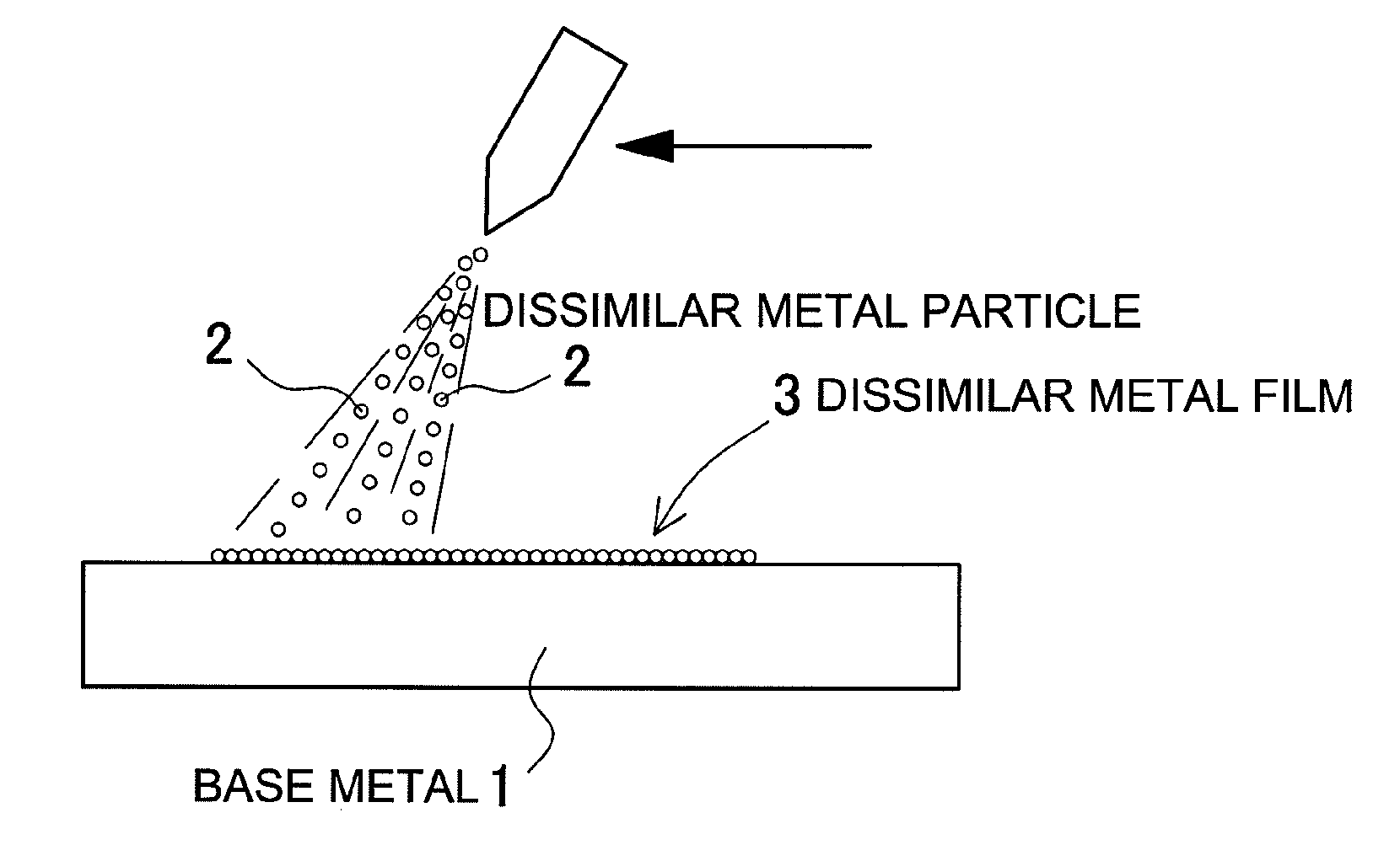
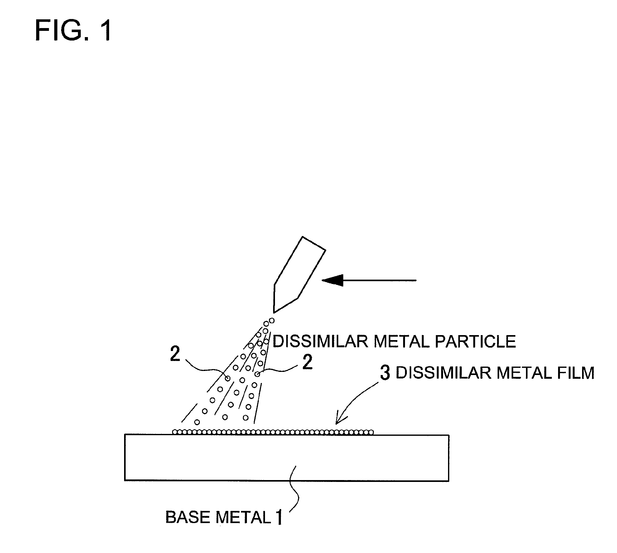
[0084]The dissimilar metal particle 2 composed of molybdenum disulfide was shot-peened on the surface of pure copper or a copper base alloy being the base metal 1. The average particle size of the dissimilar metal particle 2 was 10 μm, and the injection pressure for shot-peening operation was 1 MPa. In this shot-peening operation, the dissimilar metal film 3 of molybdenum disulfide was provided on the surface of the base metal 1.

(2) Electron Beam Irradiation Step

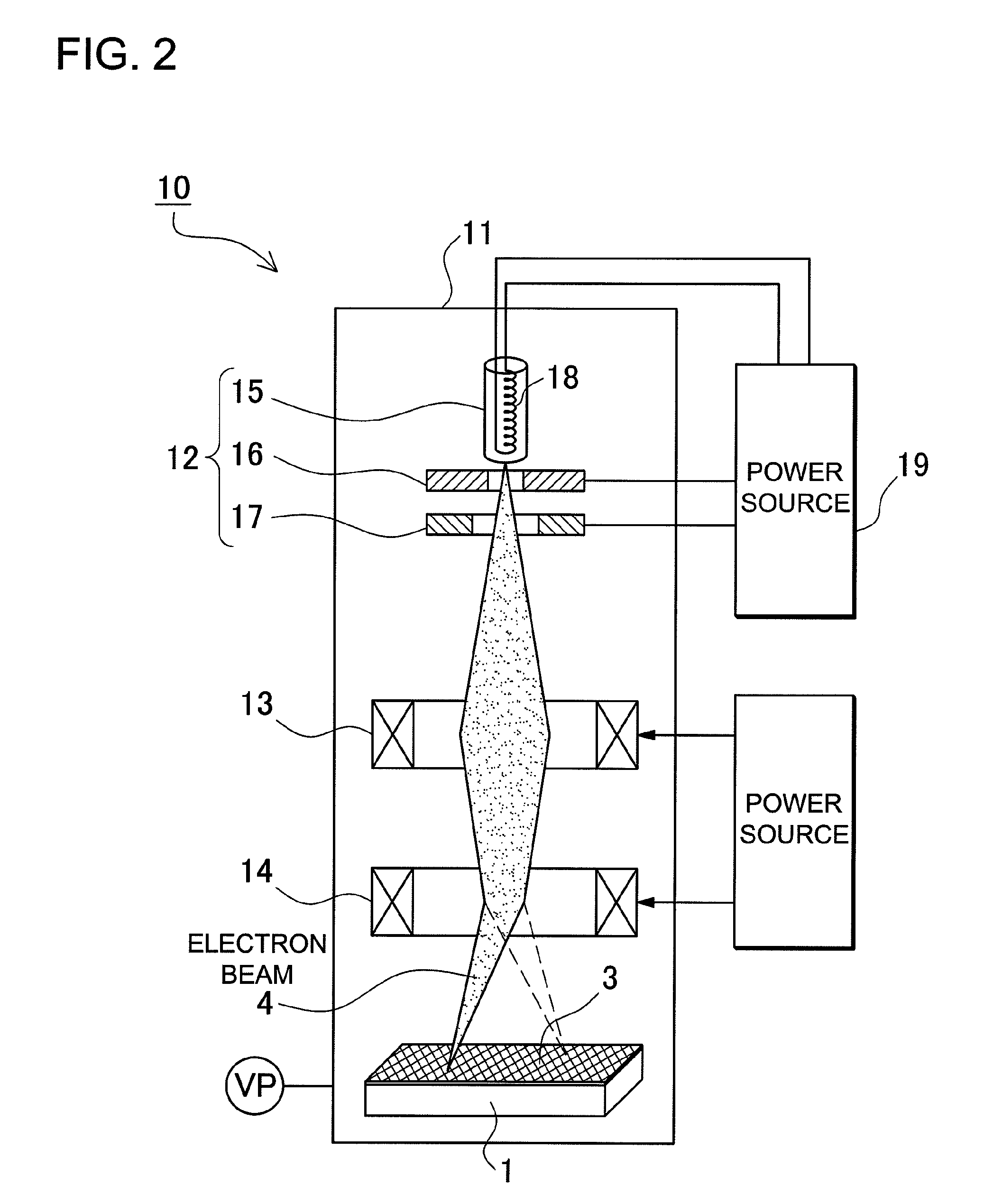
[0085]The base metal 1 whose surface was provided with the dissimilar film 3 of molybdenum disulfide was placed inside the sealed chamber 11, the sealed chamber 11 was evacuated into a vacuum state, and the surface of the base metal 1 was irradiated with the electron beam 4. Conditions for the electron beam irradiation were set as follows. The degree of vacuum in the sealed chamber was 7 Pa or less.

Diameter of the Area Spotted by the Electron Beam0.3mmAcceleration Voltage30kVBeam Current100mAScanning Are...

example 2

(1) Shot-Peening Step

[0088]The dissimilar metal particle 2 composed of tungsten was shot-peened on the surface of Ti being the base metal 1. The average particle size of tungsten being the dissimilar metal particle 2 was 20 μm, and the injection pressure for shot-peening operation was 1 MPa. In this shot-peening operation, the dissimilar metal film 3 of tungsten was provided on the surface of the base metal 1.

(2) Electron Beam Irradiation Step

[0089]The base metal 1 whose surface was provided with the dissimilar metal film 3 of tungsten was placed inside the sealed chamber 11, the sealed chamber 11 was evacuated into a vacuum state, and the surface of the base metal 1 was irradiated with the electron beam 4. Conditions for the electron beam irradiation were set as follows. The degree of vacuum in the sealed chamber was 7 Pa or less.

Diameter of the Area Spotted by the Electron Beam0.3mmAcceleration Voltage30kVBeam Current110mAScanning Area of the Electron Beam30 mm × 30 mmScanning Tim...

example 3

(1) Shot-Peening Step

[0092]SKD-11 was used as the base metal 1, and the dissimilar metal particle 2 composed of SiC was shot-peened on the surface of the base metal 1. The average particle size of the dissimilar metal particle 2 was 3 μm, and the injection pressure for shot-peening operation was 1 MPa. In this shot-peening operation, the dissimilar metal film 3 of SiC was provided on the surface of the base metal 1.

(2) Electron Beam Irradiation Step

[0093]The base metal 1 whose surface was provided with the dissimilar metal film 3 of SiC was placed inside the sealed chamber 11, the sealed chamber 11 was evacuated into a vacuum state, and the surface of the base metal 1 was irradiated with the electron beam 4. Conditions for the electron beam irradiation were set as follows. The degree of vacuum in the sealed chamber was 7 Pa or less.

Diameter of the Area Spotted by the Electron Beam0.3mmAcceleration Voltage30kVBeam Current100mAScanning Area of the Electron Beam30 mm × 30 mmScanning Ti...


PUM

PropertyMeasurementUnit
particle sizeaaaaaaaaaa
smoothnessaaaaaaaaaa

Abstract

A metal surface treatment method includes: a shot-peening step of shot-peening a dissimilar metal particle (2) on a surface of a base metal (1), the dissimilar metal particle (2) being a metal particle different from the base metal (1), to provide a dissimilar metal film (3) on the surface of the base metal (1); and an electron beam irradiation step of irradiating the surface of the base metal (1) with an electron beam (4), the surface of the base metal (1) having been provided with the dissimilar metal film (3) in the shot-peening step, to bond the dissimilar metal film (3) and the base metal (1) together.

Description

TECHNICAL FIELD[0001]The present invention relates to a metal surface treatment method in which a dissimilar metal is bonded on a surface of a base metal.BACKGROUND ART[0002]When a metal undergoes a surface treatment, a surface of the metal is processed into a state best suited for a specified use. For example, the surface is hardened, resistance to wear is improved by a reduced coefficient of friction, or the metal surface is insulated by provision of an insulation layer over the surface. As a metal surface treatment method, there has been developed a method such as a metal plating, a metal spraying, and a carburization. The plating process suffers the disadvantage that a use of various chemicals involves a cumbersome waste liquid treatment. In the spraying process as well, a surface treatment is prone to become difficult in that large-scaled equipment is required for heating metal powder into a molten state to be sprayed on a base metal. Also in the case of the carburization, this...

Claims


Application Information

Patent Timeline
Patent Type & Authority Applications(United States)
IPC IPC(8): B21D39/00
CPCC23C26/00C23C24/04
Inventor SAWAGUCHI, KAZUO
Owner KAZUO SAWAGUCHI
Why Eureka
Try Eureka