Charged particle beam extraction method using pulse voltage

a charge particle and pulse voltage technology, applied in the field of accelerators, can solve the problems of difficult to fix the beam intensity, the beam intensity of the extracted charge particle beam cannot be temporally fixed, and the time required for adjusting the charged particle beam to the extraction state, etc., to achieve the effect of significantly reducing the irradiation time period, reducing the burden on patients, and suppressing the appearance of unexpected and unnecessary side effects

Inactive Publication Date: 2012-08-09
GUNMA UNIVERSITY
View PDF4 Cites 11 Cited by
  • Summary
  • Abstract
  • Description
  • Claims
  • Application Information

AI Technical Summary

Benefits of technology

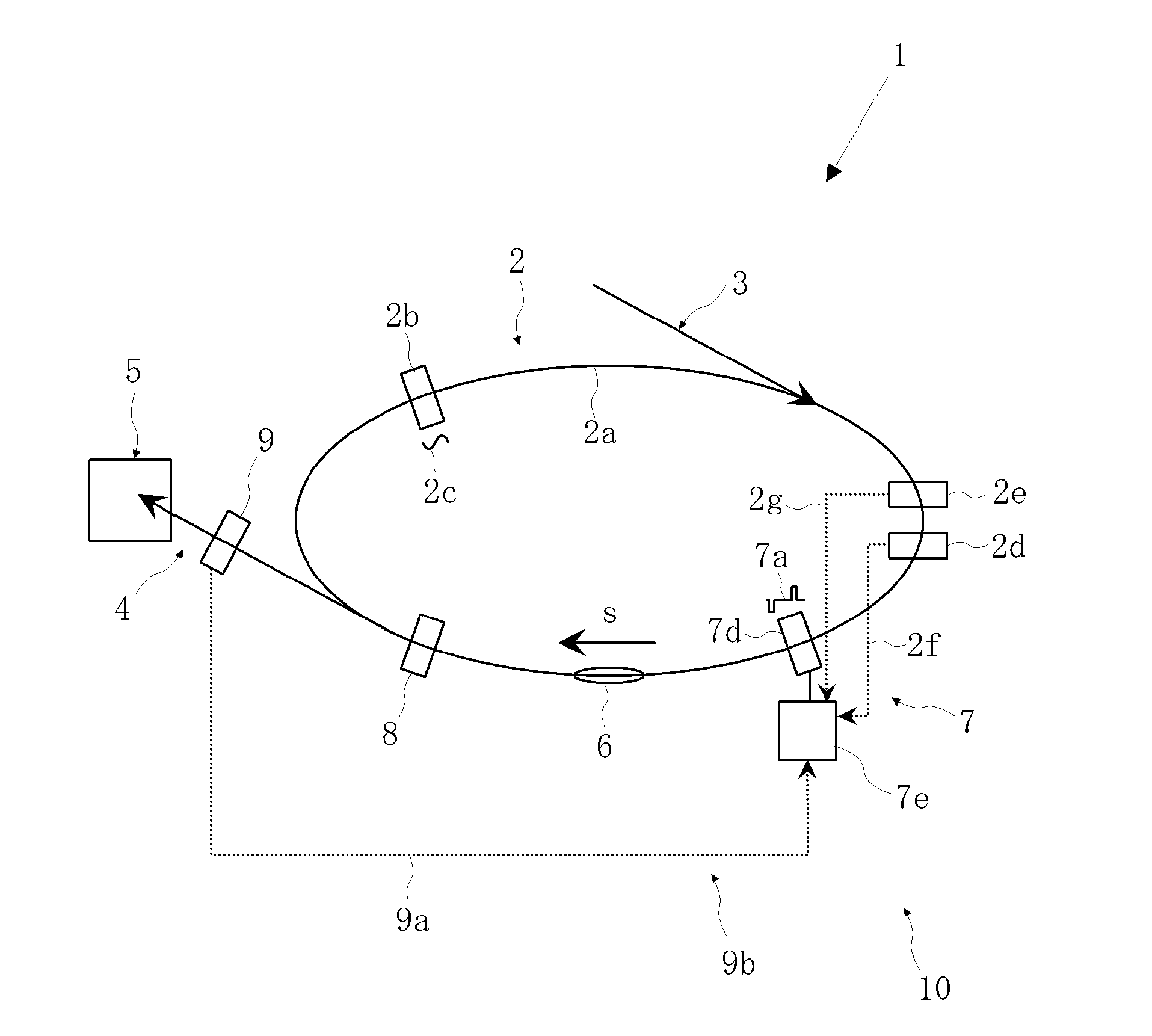
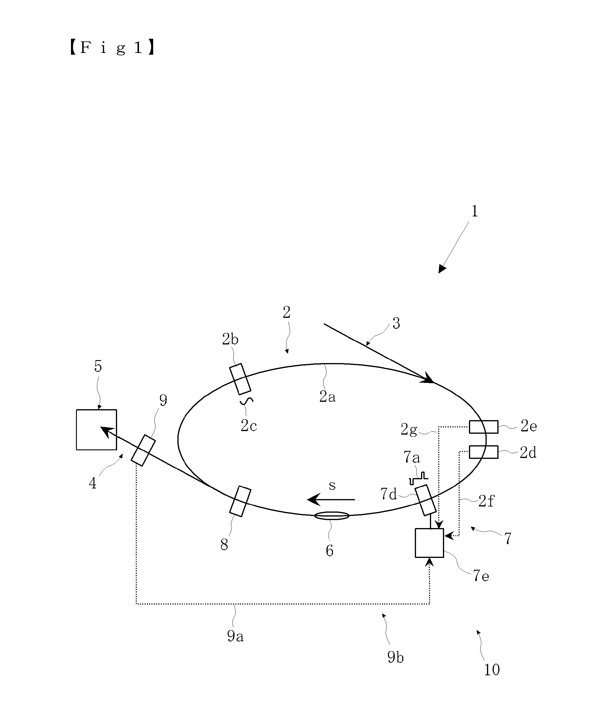
[0061]The present invention exhibits the following effects by the configurations described above. First, by applying the pulse voltage to a part of the charged particle beam, it is possible to perform control of the charged particle beam such that only a part of the charged particle beam is accelerated so as to be stably extracted at high speed. Thereby, the extraction time period can be reduced to about one tenth of the extraction time period of the conventional charged particle beam extraction method. Therefore, when the present invention is adopted to be used in a medical accelerator, the irradiation time period can be significantly reduced, so that the burden on a patient can be remarkably reduced.
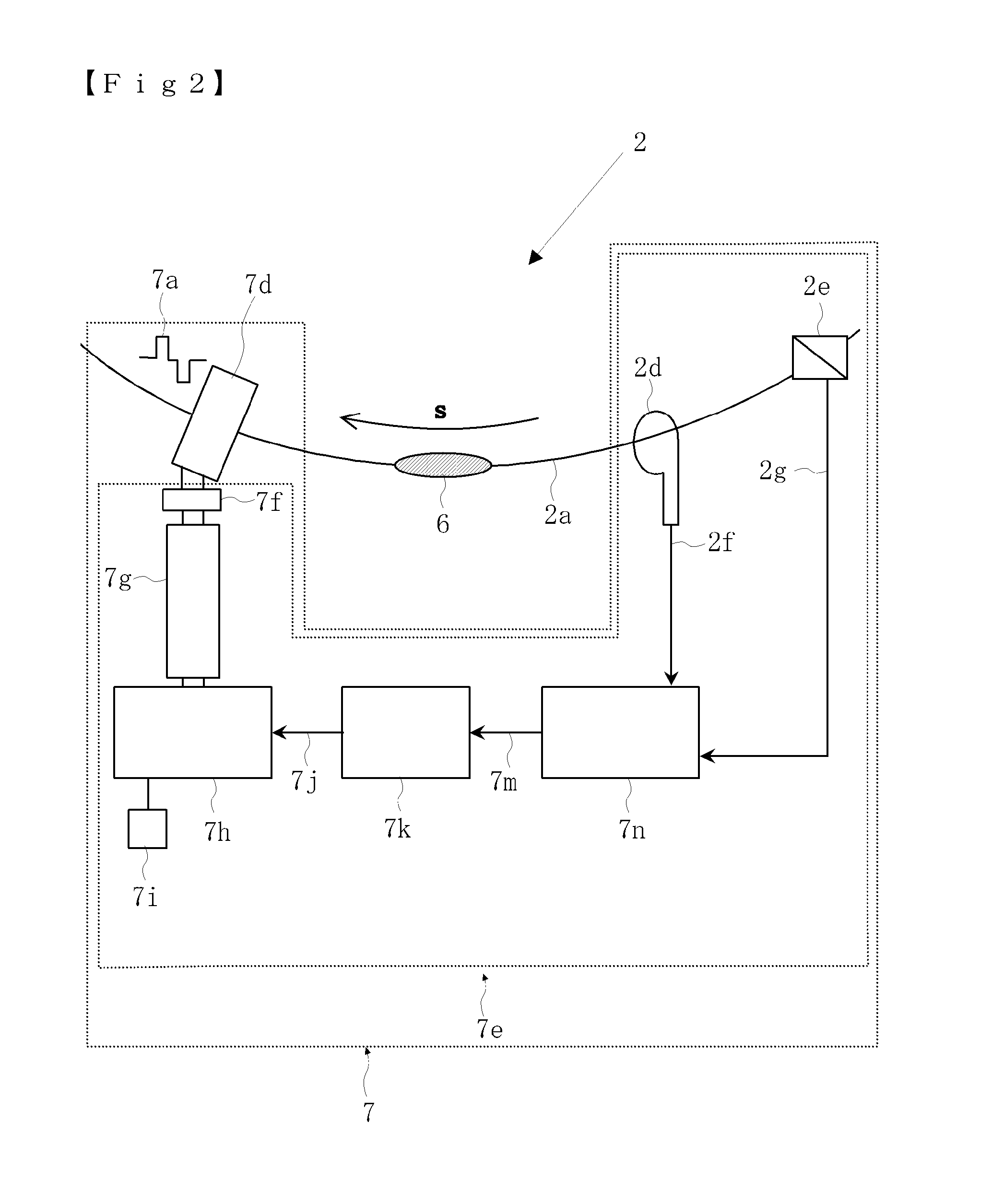
[0062]Further, a control method, in which the intensity of the extracted beam is monitored and in which the monitored beam intensity is fed back to the pattern of the pulse voltage, is adopted, and thereby the intensity of the extracted charged particle beam can be made uniform. Therefore, when the present invention is adopted to be used in a medical accelerator, the control of the intensity and irradiation dose of the charged particle beam can be performed highly precisely and instantaneously with respect to an irradiation portion. Thereby, since an irradiation dose required for a treatment can be correctly irradiated, an intended treatment effect can be surely obtained, and at the same time, the exhibition of unexpected and unnecessary side effects can be remarkably suppressed.

Problems solved by technology

Further, much time is required for adjusting the charged particle beam to the extraction state.
Further, the intensity of the extracted charged particle beam is greatly varied, so that it is difficult to fix the beam intensity.
However, in the above-described extraction methods (1) and (2), since a charged particle beam always exists in a state where the “resonance condition” is barely satisfied, and since the horizontal betatron frequency is also changed according to the change of the magnetic field due to noise, the moment when the condition that the decimal part of the resonance frequency determined by the intensity of the magnetic field reaches one third is satisfied, and the moment when the condition is not satisfied, are determined by noise.
In this way, in the conventional charged particle beam extraction method which is based on the variation of the resonance condition and in which the charged particle beam is extracted due to noise, the extraction condition, that is, the beam intensity of the extracted charged particle beam cannot be controlled to be temporally fixed.
When the required irradiation dose is irradiated inaccurately or non-uniformly in the target irradiation field, or when the irradiation dose is too much, the probability of occurrence of a serious side effect is increased.
On the other hand, when the irradiation dose is insufficient, the probability of recurrence of a tumor in the irradiated part is increased.
Therefore, in the charged particle beam irradiation therapy, the treatment time is increased mainly due to the beam intensity being temporally unstable, which imposes a very large burden on a patient.
As a result, the burden on a patient is further increased.
For a medical treatment of a patient whose general conditions are often not good, the increase in the treatment time not only causes a great pain but also becomes a problem which even determines whether or not the irradiation treatment can be applied to the patient.

Method used


Image

  • Charged particle beam extraction method using pulse voltage
  • Charged particle beam extraction method using pulse voltage
  • Charged particle beam extraction method using pulse voltage

Examples


example 1

[0113]FIG. 6 shows a comparison between a simulation result in the case (A) where the charged particle beam is not extracted and a simulation result in the case (B) where the charged particle beam is extracted by the method according to the present invention.

[0114]In the simulation, a synchrotron used for a particle beam therapy apparatus actually designed and manufactured was used as a model. Further, the length of synchrotron circulating path, the deflection magnetic field intensity, the convergence magnetic field intensity, the six pole magnetic field intensity, and the extraction position of the emission deflector were inputted and set to the parameters used in a synchrotron actually manufactured and usually operated.

[0115]The simulation was performed on the assumption that the number of charged particles is 1000, and that the number of circulation of the particles is 1000 (corresponding to 0.3 ms in real time). Note that, in verification of fundamental beam physics, the result ...

example 2

[0122]FIG. 7 shows a comparison between a simulation result of the charged particle beam intensity (broken line) obtained by the charged particle beam extraction method according to the present invention and a simulation result of the charged particle beam intensity (solid line) obtained by the conventional charged particle beam extraction method. The simulation was performed on the assumption that, after 1000 charged particles are made to circulate 1000 times, the charged particle beam is extracted respectively by the extraction method (conventional extraction method) described in Patent Literature 1, and by the extraction method according to the present invention in which the pulse voltage 7a is applied to the charged particle 6. By the simulation, a measured value of the charged particle beam intensity, which can be assumed to be measured by the beam monitor 9, was obtained for each of the extraction methods. In FIG. 7, in which the ordinate represents the beam strength [A], and ...


PUM


Abstract

A charged particle beam extraction method according to the present invention is featured in that, in a circular accelerator which accelerates a charged particle beam, a pulse voltage is applied to a part of the accelerated charged particle beam to generate a momentum deviation only in the part of the charged particle beam, in that the charged particles of a part of the charged particle beam, the charged particles having a large momentum deviation, are located in a non-stable region and in an extraction region in a horizontal phase space with respect to the traveling direction of the charged particle beam, and in that a group of the charged particles located in the non-stable region and in the extraction region are largely deviated in the horizontal direction so as to be extracted.

Description

TECHNICAL FIELD [0001]The present invention relates to an accelerator mainly configured by a circular accelerator referred to as a synchrotron, and more particularly, to a technique of extracting an accelerated charged particle beam.BACKGROUND ART [0002]Conventionally, a synchrotron using a high-frequency voltage generated from a high-frequency accelerating cavity has been used to accelerate a charged particle beam. In recent years, a method for accelerating a charged particle beam by using an induced voltage generated by an induction accelerating cell has been developed. The accelerated charged particle beam has been used for a physical experiment, a medical treatment, and the like.[0003]In the synchrotron, a charged particle beam is circulated along a design orbit while undergoing betatron oscillation. Conventionally, in order to extract an accelerated charged particle beam, “third resonance”, which is a resonance phenomenon occurring in the horizontal direction (referred to as th...

Claims


Application Information

Patent Timeline
Patent Type & Authority Applications(United States)
IPC IPC(8): H05H13/04
CPCH05H13/04H05H7/10
Inventor TORIKAI, KOTAYAMADA, SATORU
Owner GUNMA UNIVERSITY
Why Eureka
Try Eureka