
Method for correcting images output by a detector without temperature regulation and detector implementing such a method

Active Publication Date: 2012-08-09
ULIS SAS
View PDF0 Cites 14 Cited by
  • Summary
  • Abstract
  • Description
  • Claims
  • Application Information

AI Technical Summary

Benefits of technology

[0022]The object of the present invention is to propose a simple, effective method for correcting the offset variation of a TEC-less detector which does not involve any prior factory calibration.
[0039]In fact, thanks to the invention it is not necessary to provide factory calibration and this substantially reduces the cost of manufacturing the detector and the values used for correction purposes can be obtained while the detector is operating.
[0040]The invention benefits cumulatively from three advantages. The detector operates in a TEC-less mode which means that energy consumption is reduced to a minimum, factory calibration is minimised and the image quality obtained is highly satisfactory.
[0053]In other words, the quality of the offset correction table also depends on the manner in which it was computed regardless of the measured quantities used at the time it was computed. For example, if all the stored tables correspond to temperatures grouped around a given temperature, computing an offset correction table for a very different temperature by interpolating the tables that are grouped together will produce a value of relatively little relevance. Building and recurrently updating the set of raw values according to the invention thus allows optimal distribution of the temperatures of the raw value tables used to compute the offset correction table, by interpolation for example. In particular, steps are taken to ensure that said acquisition temperatures of the raw value tables are regularly staggered, for instance every 15° C., over a detector operating range that typically extends from −20° C. to +70° C.
[0060]In other words, the offset correction value is only recalculated if it is considered useful to do so in accordance with particular conditions. This avoids the additional noise associated with deliberate, very frequent recalculation in order to obtain tighter sampling of any changes in ambience and also reduces the system's power consumption. An offset correction value is thus deemed to be valid in the vicinity either side of the temperature for which it was computed and / or for a predetermined duration. It can be seen that the invention makes it possible to directly use the most relevant data to compute the offset correction value, especially data relating to the detector's current temperature.

Problems solved by technology

This type of detector has numerous advantages in terms of its manufacturing cost and implementation but also has drawbacks that limit the performance of systems that use such detectors.
In particular, there are problems with regard to the uniformity of the image obtained.
In fact, when exposed to a uniform scene, not all the bolometers deliver exactly the same signal and this results in fixed spatial noise in the image thus obtained and this noise has a seriously adverse effect on the quality of the images produced.
Nevertheless, determining an offset table is usually a tricky, time-consuming task.
Also, the offset of a bolometer depends on its temperature so that if the temperature of the bolometer deviates from the temperature at which the offset table was determined, the latter becomes irrelevant and correction becomes unsatisfactory.
This limits the extent of factory calibration.
On the other hand, the detector's energy consumption is far from optimal and this may even become a limiting factor in the context of stand-alone portable detectors.
Indeed, when the detector's ambient temperature deviates substantially from the temperature setpoint, the energy used for temperature control purposes is considerable.
Not only that, even if temperature control is implemented, it cannot ensure a perfectly constant temperature.
The quantity of offset tables is usually large in order to reap maximum benefit from the advantages of the multi-temperature control mode and this involves very protracted factory calibration of these tables and therefore considerable manufacturing costs.
In addition, in use it is found that transitional phases when there is a change from a first temperature setpoint to a second temperature setpoint generally cause a loss in the quality of the images produced by the detector.
Because temperature-controlled detectors consume large amounts of energy and are cumbersome and heavy, non-temperature controlled detectors, or “uncooled” detectors, commonly referred to as TEC-less (Thermo-Electric Cooler-less) detectors have been developed.
In the final analysis, this calibration process takes several hours and requires a thermostatted enclosure and is therefore particularly expensive for the manufacturer.
In fact, it is necessary to provide a considerable number of tables for the temperature range in question and this is expensive.
Because the use of offset tables has proved to be uneconomical, other types of correction have been designed.
However, this type of correction involves using custom-built bias circuitry for each bolometer and this makes designing the circuits of detectors much more complex and reduces fabrication yields.
Not only that, detrimental deterioration of the signal-to-noise ratio is also observed.
Also, this type of correction still requires offset tables although in limited quantities compared with the number of tables required by the first version.
However, simply measuring the electrical resistances of the pixels is not representative of all the causes of offset dispersion.
Correction performed in this way is therefore only partially effective.
On the other hand, corrections of this type are unsuitable for moving scenes because, by their very principle, such corrections eliminate or at least seriously degrade the detection of static elements or slow-moving elements in the scene.

Method used


Image

  • Method for correcting images output by a detector without temperature regulation and detector implementing such a method
  • Method for correcting images output by a detector without temperature regulation and detector implementing such a method
  • Method for correcting images output by a detector without temperature regulation and detector implementing such a method

Examples


Embodiment Construction

[0082]The following description describes one preferred embodiment of the invention which is considered optimal in terms of optimising the frequency at which the shutter is closed (and hence image loss) and correction accuracy.

[0083]It must nevertheless be appreciated that there are two separate updating conditions even if they appear to overlap in time in the embodiment that is described below: one relates to updating the offset table and one relates to updating a set of raw value tables.

[0084]Obviously, it is possible to perform execution of both these updates in parallel and independently.

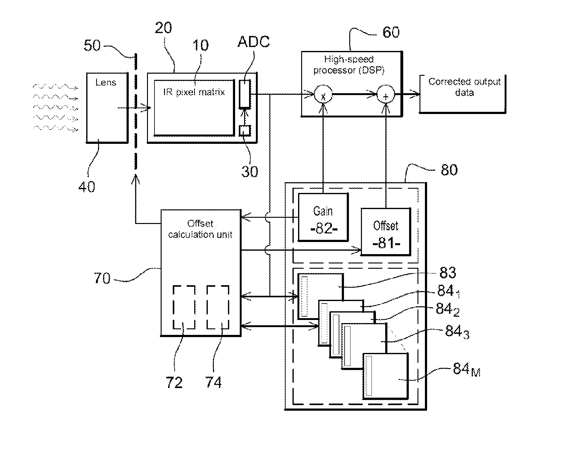
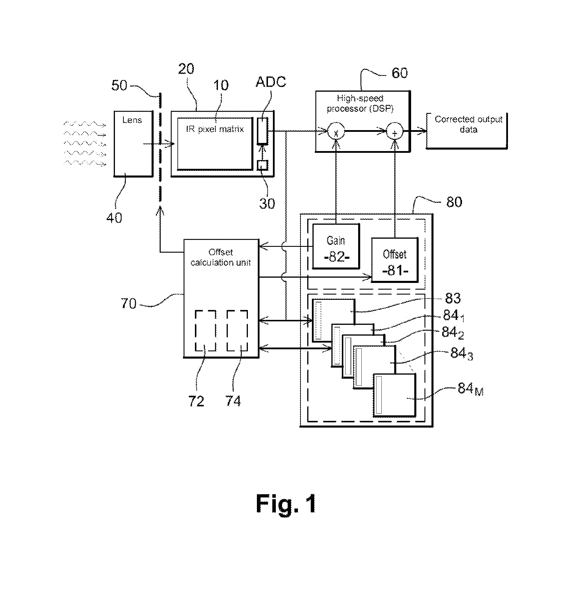
[0085]FIG. 1 schematically shows a bolometric detector according to the invention. This detector is not temperature controlled and detects radiation from a scene that is to be observed in the infrared region.

[0086]The detector comprises an array 10 of elementary thermal detectors, or bolometers, which each comprise a bolometric membrane suspended above a substrate by support, bias and thermal in...


PUM


Abstract

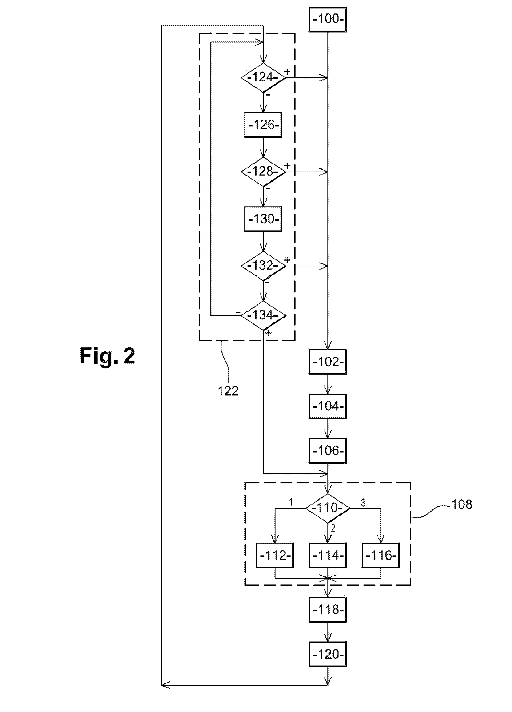
Image correction methods and systems are disclosed that correct raw values, including, subsequent to closing the shutter, acquiring a current raw value table, determining an offset correction table for the current temperature of the detector as a function of the current table and a set of stored raw value tables, and correcting the stream of raw values using the offset correction table. A maintenance process includes testing a condition for replacing a table of the current set with the current table, and if the condition is met, replacing the table of the current set with the current table. This test includes determining whether there is a new set of tables obtained by replacing a table from the current set with the current table that is more relevant than the current set with regard to subsequently determining an offset table.

Description

CROSS-REFERENCE TO RELATED APPLICATIONS[0001]The present application is a continuation of pending International Patent Application PCT / FR2010 / 052227 filed Oct. 19, 2010, which designates the United States and claims priority from French Patent Application FR 0957436, filed Oct. 22, 2009, the content of which is incorporated herein by reference.FIELD OF THE INVENTION[0002]The present invention relates to the field of infrared imaging and pyrometry using bolometers. More especially, the invention relates to the field of bolometric detectors, regardless of the detection band and the type of bolometric material used.BACKGROUND OF THE INVENTION[0003]Detectors designed for infrared imaging are conventionally produced as a one or two-dimensional array of elementary detectors, or bolometers, said bolometers taking the form of membranes suspended above a substrate, which is generally made of silicon, by means of support arms that have a high thermal resistance. This assembly of suspended mem...

Claims


Application Information

Patent Timeline
IPC IPC(8): H04N5/33G01J5/02
CPCG01J5/08G01J5/0834G01J5/20H04N5/3651G01J2005/0077H04N5/2176H04N5/33G01J5/62G01J5/0804G01J5/0805H04N25/671H04N25/63
Inventor MINASSIAN, CHRISTOPHEPISTRE, CLAIRECHIAPPA, JEAN-MARC
Owner ULIS SAS
Learn More