Switching power supply circuit and power factor controller

a technology of power factor controller and power supply circuit, which is applied in the direction of electric variable regulation, process and machine control, instruments, etc., can solve the problems of power factor drop, power factor deviation, and increase of power loss on the input lin

Active Publication Date: 2012-08-09
FUJI ELECTRIC CO LTD
View PDF7 Cites 40 Cited by
  • Summary
  • Abstract
  • Description
  • Claims
  • Application Information

AI Technical Summary

Benefits of technology

[0032]According to the present invention, a switching power supply circuit and a power factor controller which can perform switching from critical operation to continuous operation without an auxiliary winding can be provided.

Problems solved by technology

These components are a source of high-frequency noise and cause a drop in power factor.
However, the phase of current may deviate from the phase of voltage due to a load other than a resistor.
This causes an increase in power loss on an input line.
Therefore, the critical current control method is used by a power factor controller the power consumption of which is low, for example, about 250 W or less, and is not suitable for a power factor controller the power consumption of which is higher than 250 W.

Method used


Image

  • Switching power supply circuit and power factor controller
  • Switching power supply circuit and power factor controller
  • Switching power supply circuit and power factor controller

Examples


example 1

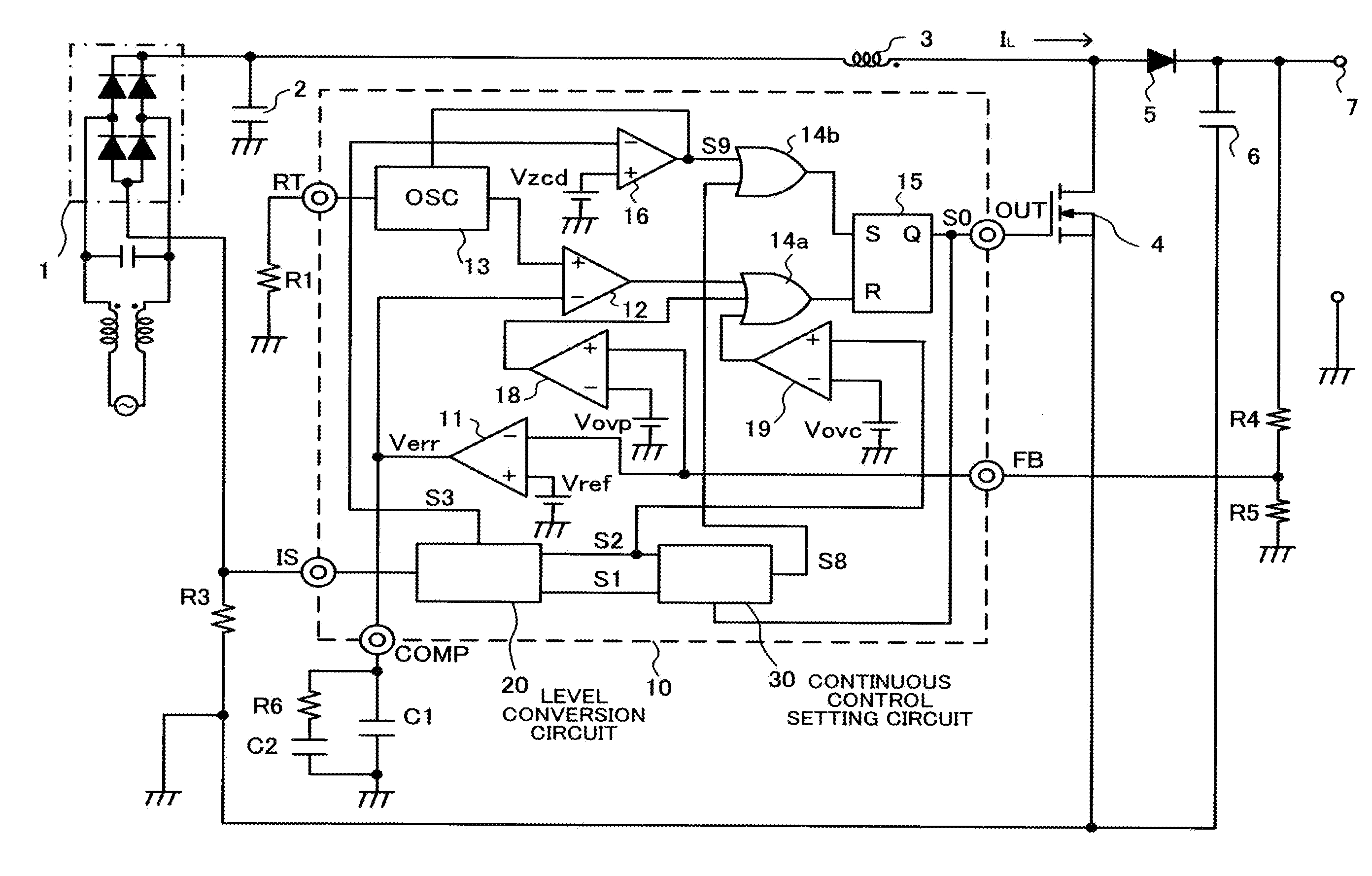
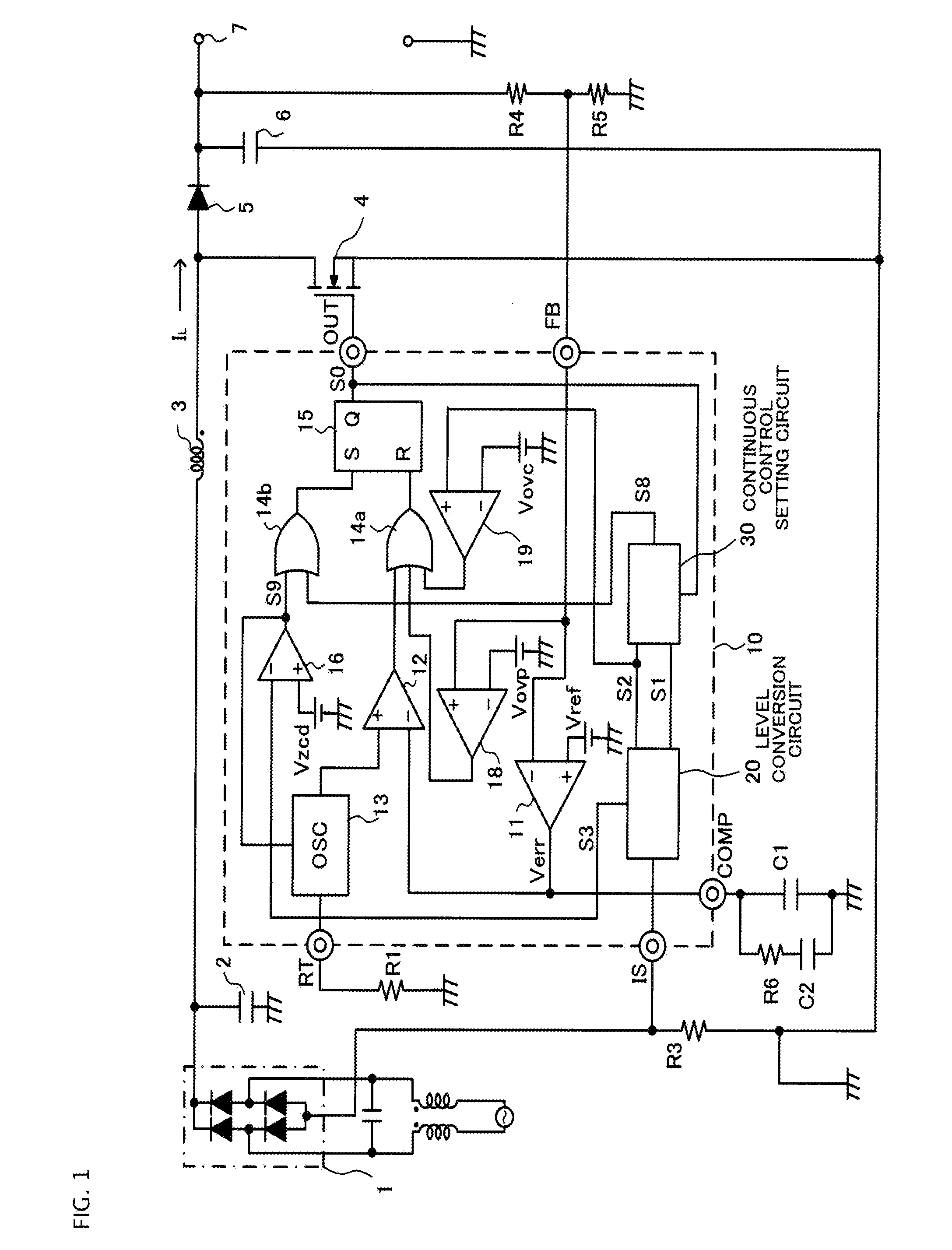
[0047]FIG. 1 is a circuit diagram of a switching power supply circuit according to a first embodiment. Components corresponding to those included in the switching power supply circuit illustrated in FIG. 13 as a conventional example will be marked with the same reference symbols and repetitive Descriptions will be omitted.

[0048]The switching power supply circuit illustrated in FIG. 1 includes a full-wave rectifier 1 which full-wave rectifies alternating power-supply voltage and which outputs a pulsating current, and an inductor 3 connected to the full-wave rectifier 1. The switching power supply circuit supplies determined direct-current output voltage from alternating power supply to a load. The switching power supply circuit on-off controls a switching element 4 by a power factor controller 10 which performs switching between critical operation and continuous operation without an auxiliary winding. Accordingly, the power factor controller 10 illustrated in FIG. 1 differs from the ...


PUM


Abstract

The switching power supply circuit includes a full-wave rectifier (1) which full-wave rectifies alternating power-supply voltage to output a pulsating current, and an inductor (3) connected to the full-wave rectifier (1). A level conversion circuit (20) includes a plurality of resistors connected in series, and converts inductor current detection voltage to a first current level signal and a second current level signal (S1 and S2) which are different in voltage level and which are proportional to inductor current. A continuous control setting circuit (30) generates a reference potential signal a phase of which is approximately the same as a phase of alternating input voltage from the first current level signal (S1) and compares a voltage level of the reference potential signal with a voltage level of the second current level signal (S2) to output a second set pulse (S8) that specifies timing at which a switching element (4) turns on.

Description

TECHNICAL FIELD[0001]This invention relates to a switching power supply circuit for supplying determined direct-current output voltage from alternating power supply to a load and a power factor controller and, more particularly, to a switching power supply circuit and a power factor controller which can perform switching between a critical current control method and a continuous current control method.BACKGROUND ART[0002]With many electronic devices to which commercial alternating power-supply voltage (AC 100 to 240 V) is supplied, a switching power supply circuit is used for obtaining direct-current voltage for driving an internal electronic circuit. Accordingly, the switching power supply circuit needs a rectifying circuit for converting commercial alternating power-supply voltage to direct-current voltage. If power factor improvement is not made, current flows to a smoothing capacitor connected to the rectifying circuit only at the time of input voltage being near a peak. As a re...

Claims


Application Information

Patent Timeline
Patent Type & Authority Applications(United States)
IPC IPC(8): H02M3/155H02M7/04
CPCH02M1/4225Y02B70/126H02M3/156Y02B70/10
Inventor SUGAWARA, TAKATO
Owner FUJI ELECTRIC CO LTD
Why Eureka
Try Eureka