Multiple modulation heterodyne infrared spectroscopy

a heterodyne infrared and multimodulation technology, applied in the field of high-localized infrared (ir) spectra, can solve the problems of limiting the technique for some applications, addressing any specific practical implementation, and reducing the resolution of conventional ir spectroscopy and microscopy

Active Publication Date: 2012-08-09
BRUKER NANO INC
View PDF8 Cites 35 Cited by
  • Summary
  • Abstract
  • Description
  • Claims
  • Application Information

AI Technical Summary

Benefits of technology

[0013]In other embodiments, the peak of the cantilever oscillation at fc2 has a half width of Fc2hw, and fm is chosen to be greater than fc2hw, to ensure that f2 will not excite a significant cantilever response at fc2 absent sample / tip interaction at fm. In further embodiments fc2 / fm is not equal to an integer, to avoid direct excitation of the cantilever at resonance f2c due to harmonics of fm being equal to fc2. fm is preferably chosen to be a pulse rate of a pulsed IR laser low enough to result in power sufficient for the measurements.

Problems solved by technology

Conventional IR spectroscopy and microscopy, however, have resolution on the scale of many microns, limited by optical diffraction.
Although the spatial resolution obtained using this technique for IR spectroscopic identification of sample composition is superior to more conventional techniques, certain spatial resolution factors have been identified that might limit the technique for some applications.
Wickramasinghe also suggested that it should be possible to make similar measurements at other radiation frequencies, including infrared, but he did not address any specific practical implementations.
In practice, Wickramasinghe's suggestion that the technique could be used in the IR is far from straightforward.
As will be described below, this is impractical in the IR.
A variety of modulation techniques exist, including photoelastic modulators, electro-optic modulators, acousto-optic modulators, mechanical choppers, piezo electrically actuated mirrors, etc, but each of these suffer from one or more limitations.
Some modulators work at a limited wavelength range thus limiting the spectroscopic range available and some techniques operate only over a limited range of modulation frequencies.

Method used


Image

  • Multiple modulation heterodyne infrared spectroscopy
  • Multiple modulation heterodyne infrared spectroscopy
  • Multiple modulation heterodyne infrared spectroscopy

Examples


Embodiment Construction

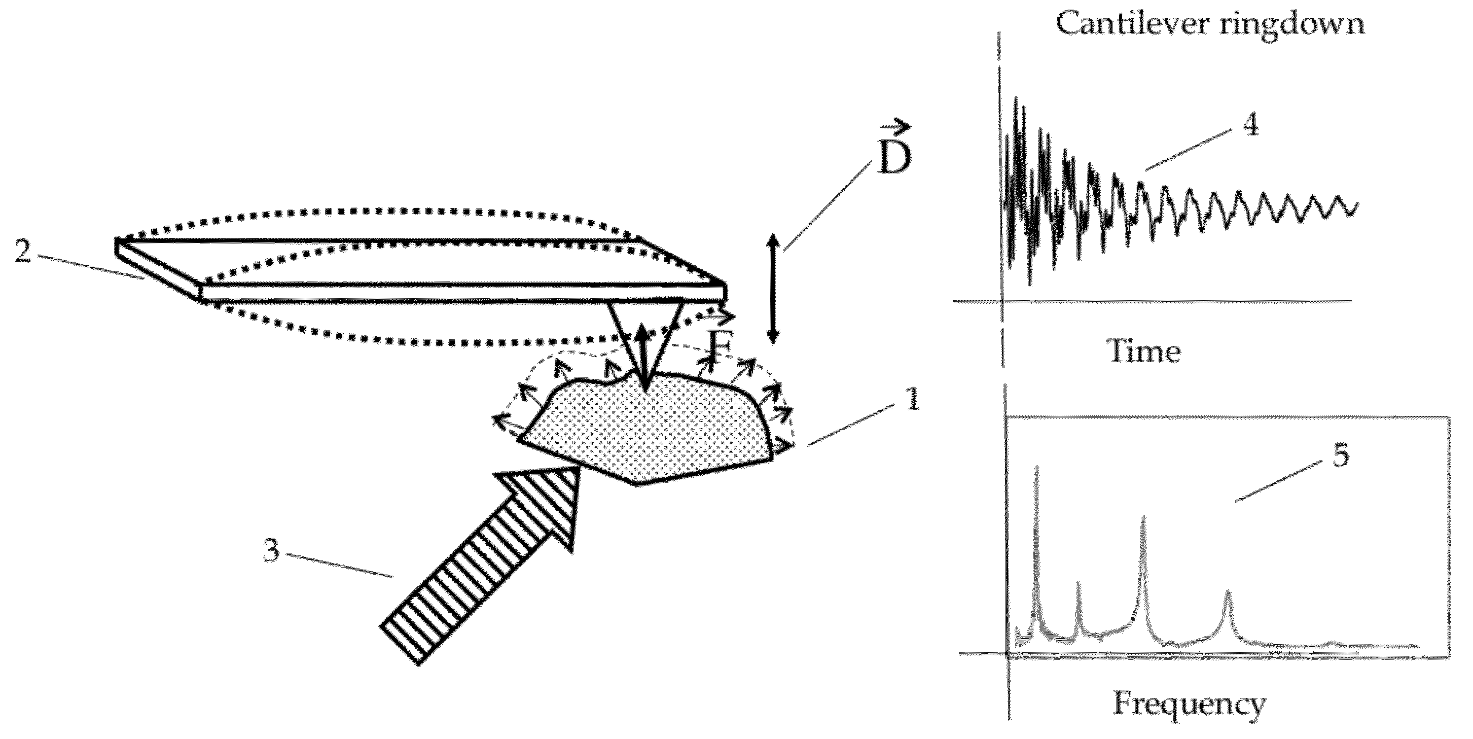
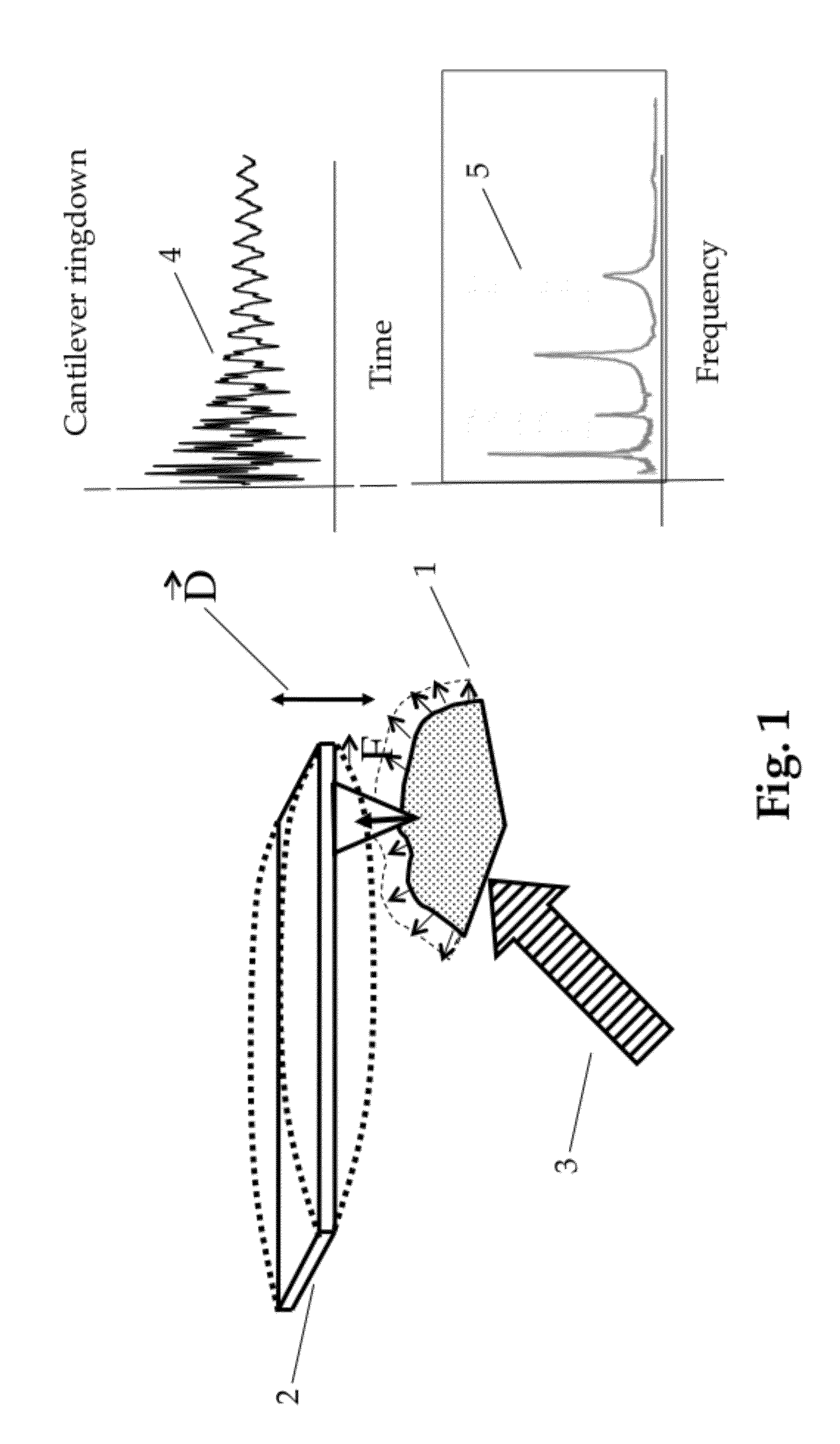
[0022]Referring to FIG. 1 the basics for a prior art PTIR system are shown. Sample 1 is probed by an AFM with a cantilever probe 2. The interaction between the probe and sample may be contact, non-contact, near contact, intermittent contact and / or tapping or other method of interaction that generates a measurable probe response as a function of the interaction. A pulsed IR beam 3 is directed at the sample 1. Adsorption of the beam will cause localized heating in the sample resulting in a thermal expansive interaction with the probe tip resulting in a decaying contact resonance ringdown 4. The characteristics of this ringdown waveform, which may be characterized by a spectrum of the waveform 5, depend on the absorption properties of the material under the tip. If the measurement is repeated at multiple source wavelengths as absorption spectra may be produced, leading to identification of the material in the immediate vicinity of the probe tip.

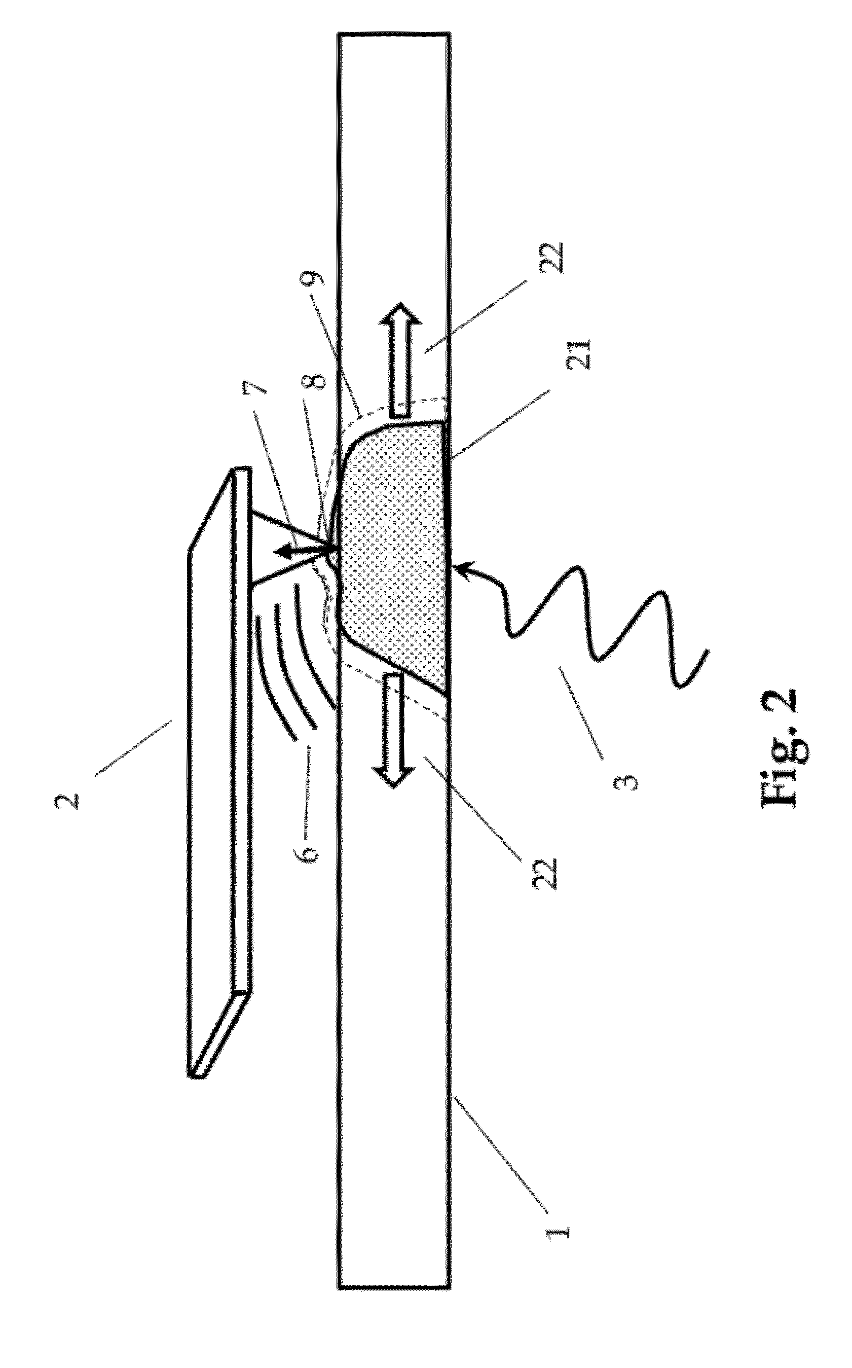
[0023]FIG. 2 illustrates that the forces ...


PUM


Abstract

A heterodyne detection technique for highly localized IR spectroscopy based on an AFM. A pulsed IR source illuminates a sample and causes contact resonance of an AFM probe, which is a function of localized absorption. The probe is operated in intermittent contact mode and is therefore oscillated at a resonance frequency. A secondary oscillation is mixed in to the probe oscillation such that the sum of the secondary oscillation and the IR source pulse frequency is near another harmonic of the probe. A mixing effect causes measurable probe response at the other harmonic allowing data to be taken away from the pulse frequency, resulting in background effect rejection and improved spatial resolution.

Description

RELATED APPLICATIONS[0001]This Application claims priority to U.S. Provisional Application Serial No. 61 / 460,666, filed Jan. 5, 011FEDERALLY SPONSORED RESEARCH[0002]This invention was made with United States Government support under ATP Award 70NANB7H7025 awarded by the National Institute of Standards and Technology (NIST) and Award 0944400 awarded by the National Science Foundation. The United States Government has certain rights in the invention.SEQUENCE LISTING[0003]Not ApplicableBACKGROUND OF THE INVENTION[0004]This invention is related to highly localized Infrared (IR) spectra on a sample surface utilizing an Atomic Force Microscope (AFM) and a variable wavelength modulated IR source, and specifically to a multiple frequency probe excitation technique leading to improved rejection of background effects and improved spatial resolution.[0005]IR spectroscopy is a useful tool in many analytical fields such as materials and life sciences. Conventional IR spectroscopy and microscopy,...

Claims


Application Information

Patent Timeline
Patent Type & Authority Applications(United States)
IPC IPC(8): G01Q20/02
CPCB82Y35/00G01N21/171G01Q60/34G01Q30/02G01N21/3563
Inventor PRATER, CRAIGKJOLLER, KEVIN
Owner BRUKER NANO INC
Why Eureka
Try Eureka