Negative pressure wound closure device

Active Publication Date: 2012-08-16
UNIV OF MASSACHUSETTS
View PDF5 Cites 139 Cited by
  • Summary
  • Abstract
  • Description
  • Claims
  • Application Information

AI Technical Summary

Benefits of technology

[0017]By using the negative pressure wound closure device of the invention, patients with large or severe wounds are able to be discharged or engage in rehabilative physical therapy, changed at home and then brought ba

Problems solved by technology

Prior negative pressure devices did not assist

Method used


Image

  • Negative pressure wound closure device
  • Negative pressure wound closure device
  • Negative pressure wound closure device

Examples


Embodiment Construction

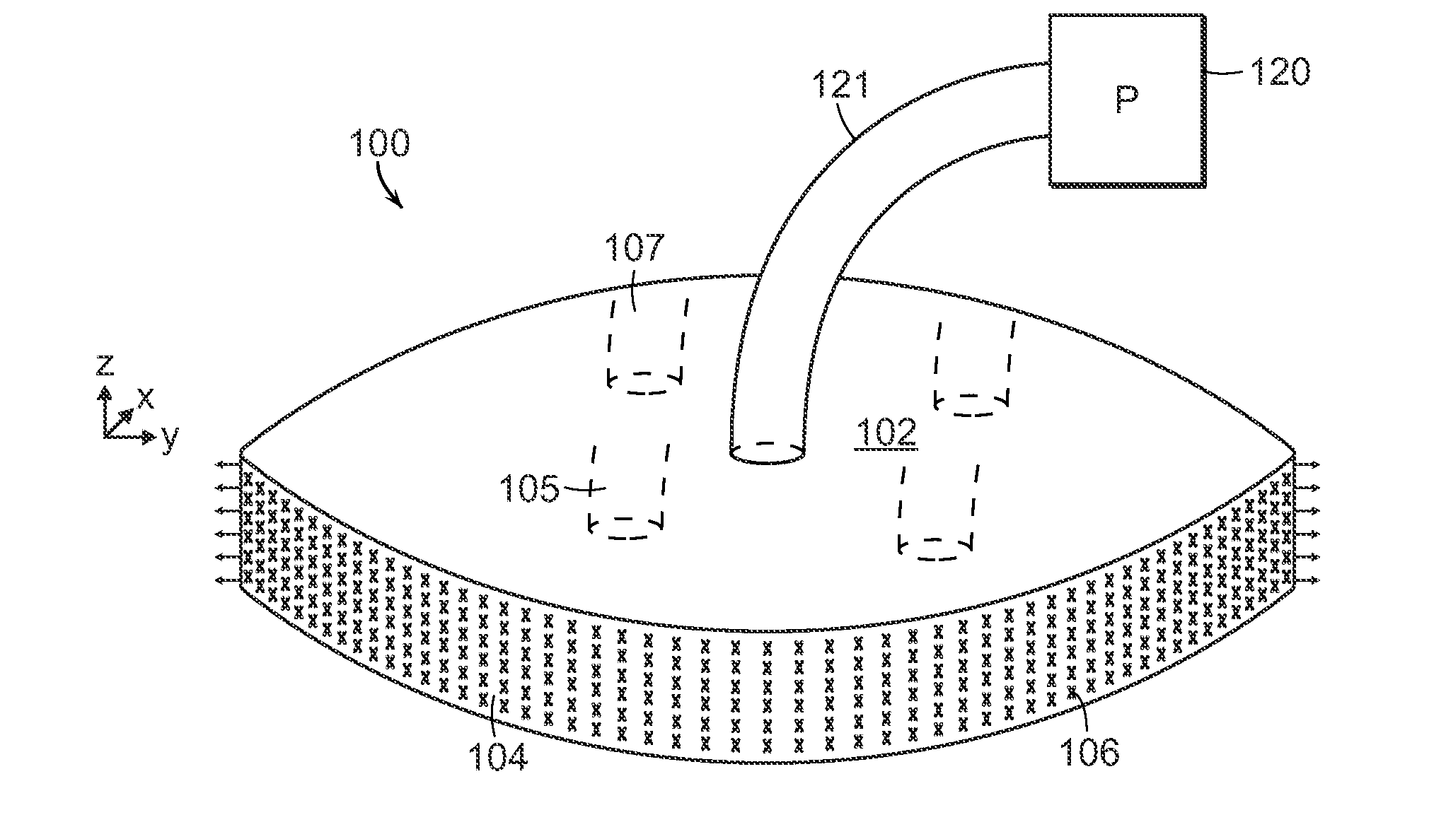
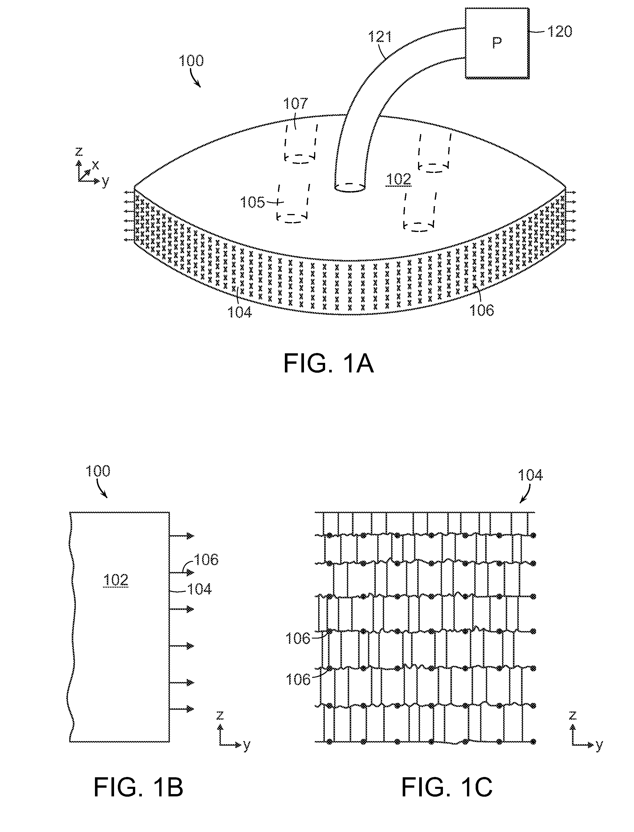
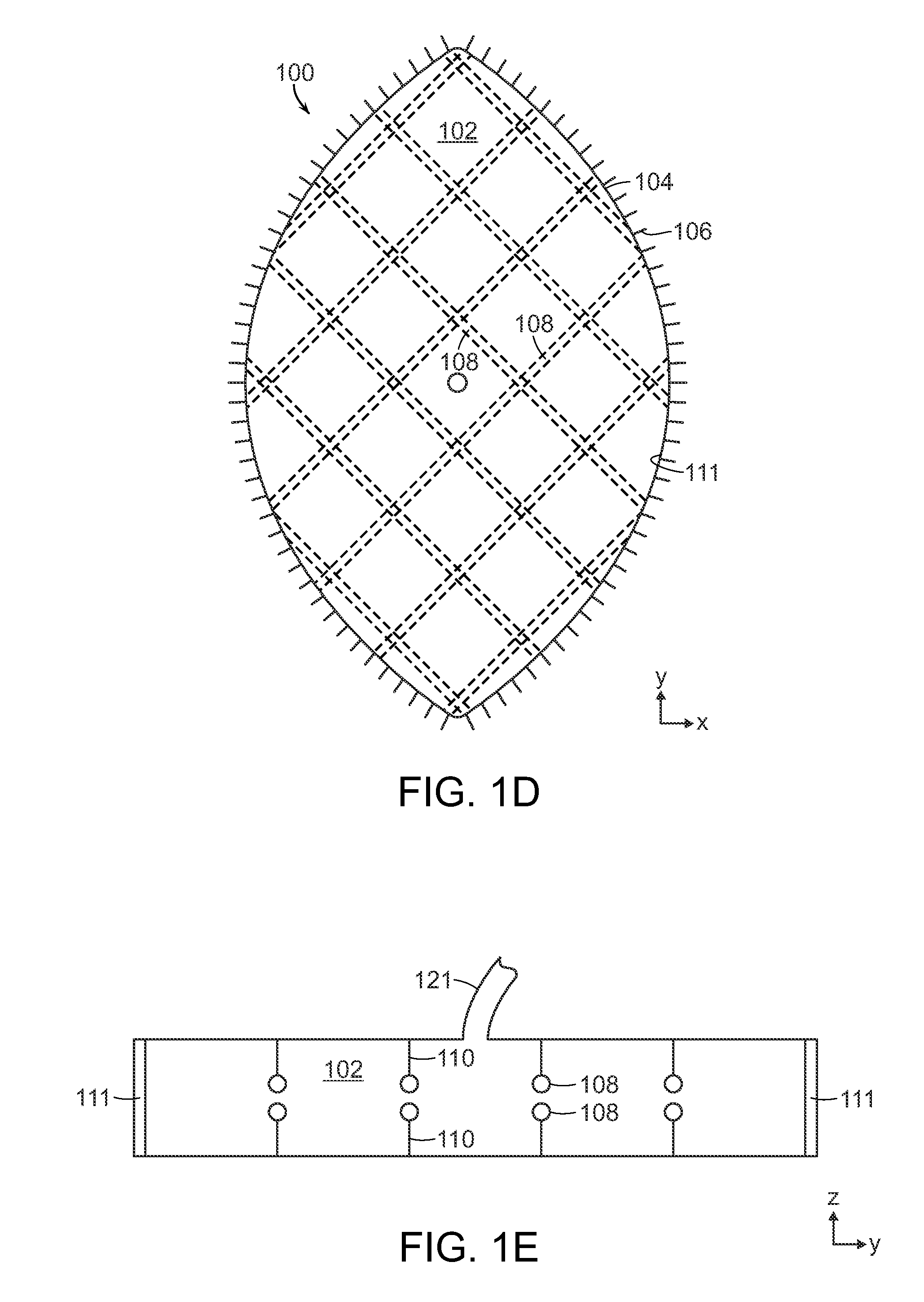
[0040]FIGS. 1A-1F illustrate an embodiment of a wound closure device 100 of the present invention. The device 100 includes a wound filler material 102 that is sized and shaped to fit within a wound opening of a human or animal patient. In preferred embodiments, the filler material 102 is a porous, biocompatible material, such as an open cell polyurethane foam. The filler material 102 is also preferentially collapsible, meaning that its size can be reduced along at least one dimension (e.g., length, width, height) by applying a negative pressure to the filler material 102, while at the same time inhibiting contractions or contracting at a slower rate in another direction.

[0041]Extending over at least one surface of the filler material 102, and preferably extending over an outer perimeter surface of the filler material 102 is a tissue grasping surface 104. In one embodiment, the tissue grasping surface 104 is a flexible covering, such as a mesh film, that is secured to the outer perim...


PUM


Abstract

The present invention relates to a negative pressure wound closure system and methods for using such a system. Preferred embodiments of the invention facilitate closure of the wound by preferentially contracting to provide for movement of the tissue. Preferred embodiments can utilize tissue grasping elements to apply a wound closing force to the tissue.

Description

CROSS REFERENCE TO RELATED APPLICATION[0001]This application claims the priority to U.S. Application No. 61 / 439,525, filed Feb. 4, 2011. The entire contents of the above application being incorporated herein by reference.BACKGROUND OF THE INVENTION[0002]A number of techniques have been developed for treatment of wounds, including wounds resulting from accident and wounds resulting from surgery. Often, wounds are closed using sutures or staples. However, inserting these mechanical closure techniques requires making additional punctures or wounds to the skin, which can result in tissue injury and in the case of excess swelling, possible ischemia and tissue loss. Also, mechanical wound closures such as staples and sutures can cause highly-localized stresses at the insertion points that can impede and damage the normal wound healing processes of the skin.[0003]In recent years, there has been increased interest in using negative pressure devices for the treatment of wounds. Negative pres...

Claims


Application Information

Patent Timeline
IPC IPC(8): A61B17/03A61M1/00
CPCA61B17/08A61B2017/081A61M1/0088A61F13/00068A61F2013/00548A61F2013/00536A61F2013/0054A61F2013/00544A61F2013/00174A61B17/0057A61B2017/00561A61B2017/00654A61M1/84A61M1/90A61M1/916A61B17/00A61M1/08
Inventor DUNN, RAYMOND
Owner UNIV OF MASSACHUSETTS
Why Eureka
Try Eureka