Stentless Support Structure

a support structure and stent technology, applied in the field of stentless support structure, can solve the problems of stenosis, narrowing of the passageway through the valve, heart failure and ultimately death, and great discomfor

Active Publication Date: 2012-08-16
EDWARDS LIFESCIENCES CORP
View PDF8 Cites 30 Cited by
  • Summary
  • Abstract
  • Description
  • Claims
  • Application Information

AI Technical Summary

Benefits of technology

[0020]The present invention accomplishes the aforementioned objects by providing a tubular mesh support structure for a native lumen that is capable of being delivered via a very small diameter delivery catheter. The tubular mesh is formed one or more fine strands braided together into an elongate tube. The strands may be fibrous, non-fibrous, multifilament, or monofilament. The strands exhibit shape memory such that the elongate tube may be formed into a desired folded shape, then stretched out into a very small diameter, elongated configuration. The small diameter, elongated configuration makes a very small diameter delivery catheter possible.
[0021]Upon deployment, the elongated tube is slowly pushed out of the delivery catheter, where it gradually regains its folded, constructed configuration. The tube conforms to the internal geometries of the target vessel. In addition, the braid effectively traps all emboli that may be released from the vessel walls.
[0022]As the tube continues to be pushed from the delivery catheter, it begins to fold in upon itself as it regains its constructed configuration. As it folds in upon itself, the forces exerted by each layer add together, making the structure incrementally stronger. Thus, varying levels of strength may be achieved without changing the elongated diameter of the device.

Problems solved by technology

Such immobility also may lead to a narrowing, or stenosis, of the passageway through the valve.
The increased resistance to blood flow that a stenosed valve presents can eventually lead to heart failure and ultimately death.
Naturally, this is a heavily invasive procedure and inflicts great trauma on the body leading usually to great discomfort and considerable recovery time.
One particular drawback with the percutaneous approach disclosed in the Andersen '614 patent is the difficulty in preventing leakage around the perimeter of the new valve after implantation.
Since the tissue of the native valve remains within the lumen, there is a strong likelihood that the commissural junctions and fusion points of the valve tissue (as pushed apart and fixed by the stent) will make sealing around the prosthetic valve difficult.
In practice, this has often led to severe leakage of blood around the stent apparatus.
Other drawbacks of the Andersen '614 approach pertain to its reliance on stents as support scaffolding for the prosthetic valve.
First, stents can create emboli when they expand.
Second, stents are typically not effective at trapping the emboli they dislodge, either during or after deployment.
Third, stents do not typically conform to the features of the native lumen in which they are placed, making a prosthetic valve housed within a stent subject to paravalvular leakage.
Fourth, stents are subject to a tradeoff between strength and compressibility.
Fifth, stents cannot be retrieved once deployed.
Sixth, the inclusion of the valve within the stent necessarily increases the collapsed diameter of the stent-valve complex and increases the caliber of the material that must be delivered into the vasculature.
The force is usually strong enough to crack or pop thrombosis, thereby causing pieces of atherosclerotic plaque to dislodge and become emboli.
As to the second drawback, if emboli are created, expanded stents usually have members that are too spaced apart to be effective to trap any dislodged material.
The third drawback is due to the relative inflexibility of stents.
Due to the non-conforming nature of stents, this seal is hard to achieve, especially when displacing stenosed valve leaflets.
The fourth drawback is the tradeoff between compressibility and strength.
Larger delivery catheters are more difficult to maneuver to a target area and also result in more trauma to the patient.
The fifth drawback of stents is that they are not easily retrievable.
Thus, if a physician is unsatisfied with the deployed location or orientation of a stent, there is little he or she can do to correct the problem.
The sixth drawback listed above is that the combination of the valve within the stent greatly increases the size of the system required to deliver the prosthetic device.
As a result, the size of the entry hole into the vasculature is large and often precludes therapy, particularly in children, smaller adults or patients with pre-existing vascular disease.

Method used


Image

  • Stentless Support Structure
  • Stentless Support Structure
  • Stentless Support Structure

Examples


Embodiment Construction

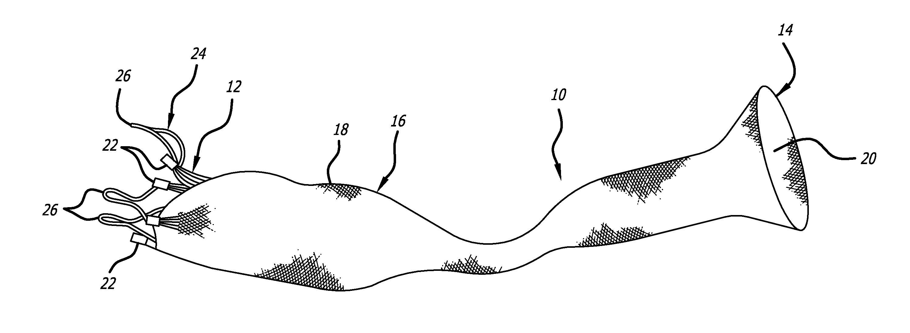
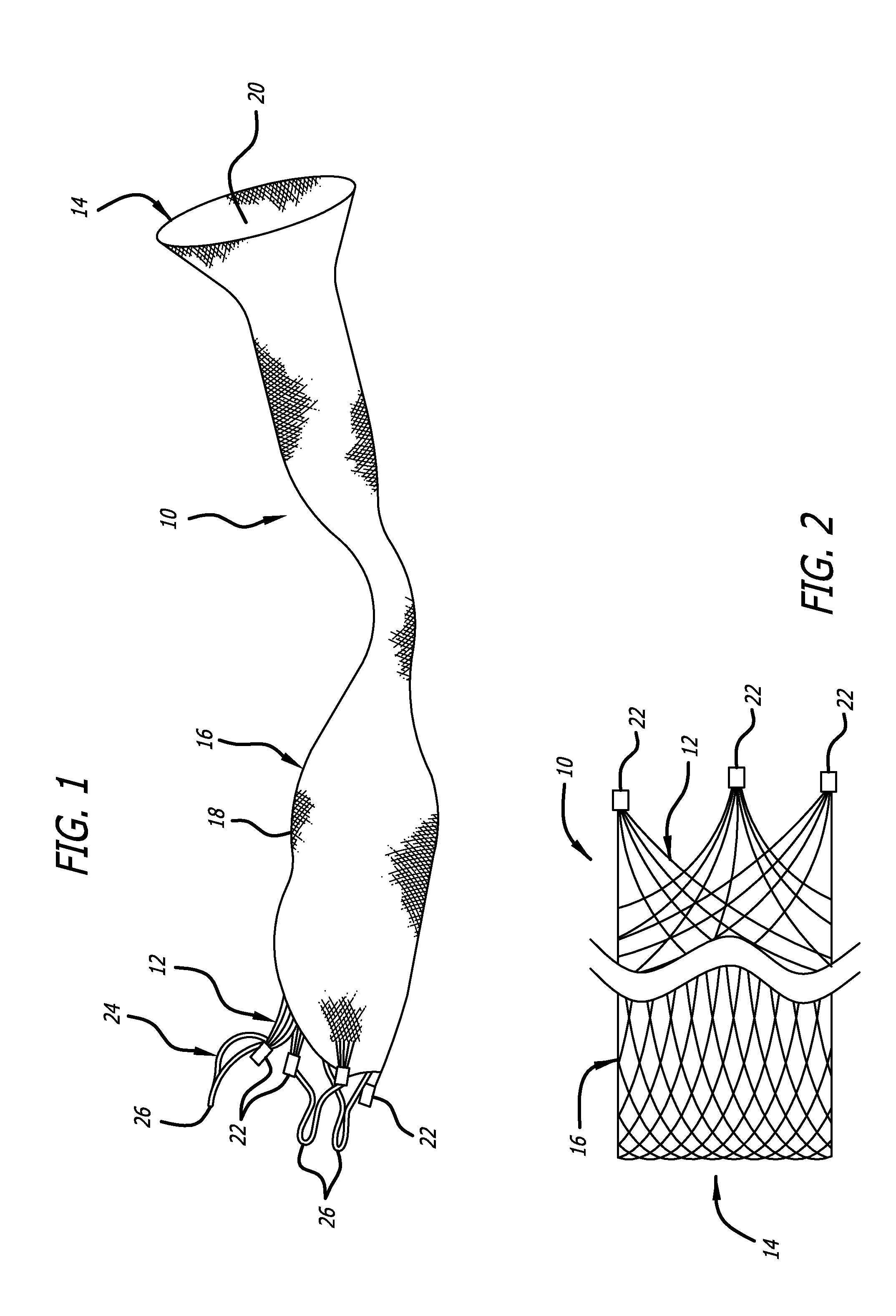
[0045]Referring now to the Figures and first to FIG. 1, there is shown a stentless support structure 10 of the present invention in an extended configuration. The valve support 10 includes a first end 12, a second end 14 and an elongate tubular body 16 extending between the first end 12 and the second end 14.

[0046]The elongate tubular body 16 is preferably formed from one or a plurality of braided strands 18. The braided strands 18 are strands of a super-elastic or shape memory material such as Nitinol. The strands are braided to form a tube having a central lumen 20 passing therethrough.

[0047]In one embodiment, the tubular body 16 is folded in half upon itself such that the second end 14 becomes a folded end and the first end 12 includes a plurality of unbraided strands. The tubular body 16 is thus two-ply. The unbraided strands of the first end 12 are gathered and joined together to form a plurality of gathered ends 22. The gathered ends 22 may be used as commissural points for at...


PUM


Abstract

A stentless support structure capable of being at least partly assembled in situ. The support structure comprises a braided tube that is very flexible and, when elongated, becomes very long and very small in diameter, thereby being capable of placement within a small diameter catheter. The support structure is preferably constructed of one or more thin strands of a super-elastic or shape memory material such as Nitinol. When released from the catheter, the support structure folds itself into a longitudinally compact configuration. The support structure thus gains significant strength as the number of folds increase. This radial strength obviates the need for a support stent. The support structure may include attachment points for a prosthetic valve.

Description

CROSS-REFERENCE TO RELATED DOCUMENTS[0001]This application is a continuation of U.S. patent application Ser. No. 11 / 443,814 filed May 30, 2006 entitled Stentless Support Structure, which is related to and claims priority benefit of U.S. Provisional Patent Application Ser. No. 60 / 685,349, filed May 27, 2005, entitled Stentless Support Structure, by Wilson et al. and U.S. Provisional Patent Application Ser. No. 60 / 709,595, filed Aug. 18, 2005, entitled Stentless Support Structure by Wilson et al. These applications are also hereby incorporated by reference herein. This application also incorporates by reference U.S. patent application Ser. No. 11 / 442,371 entitled Intravascular Cuff filed by Applicant on May 30, 2006 and U.S. Provisional Patent Application Ser. No. 60 / 685,433, filed May 27, 2005, entitled Intravascular Cuff.BACKGROUND OF THE INVENTION[0002]There has been a significant movement toward developing and performing cardiovascular surgeries using a percutaneous approach. Thro...

Claims


Application Information

Patent Timeline
Patent Type & Authority Applications(United States)
IPC IPC(8): A61F2/06A61F2/24A61F2/90
CPCA61F2/2418A61F2250/0039A61F2/2436A61F2230/0067A61F2/06A61F2/95A61F2220/0075A61F2/90A61F2210/0076A61F2220/0025A61F2230/001A61F2230/0013
Inventor THILL, GARY A.WILSON, ROBERT FOSTERGAINOR, JOHNBANICK, CHRISTOPHER M.
Owner EDWARDS LIFESCIENCES CORP
Why Eureka
Try Eureka