Multi-Shoot Launcher Comprising a Load-Redirecting Pusher Plate

a technology of pusher plate and thruster, which is applied in the field of multi-shoot launchers comprising a, can solve the problems of extreme static load on the projectiles that remain in the barrel, and achieve the effects of reducing drag, much higher speed, and greater distan

Inactive Publication Date: 2012-08-23
LOCKHEED MARTIN CORP
View PDF1 Cites 2 Cited by
  • Summary
  • Abstract
  • Description
  • Claims
  • Application Information

AI Technical Summary

Benefits of technology

[0017]In some embodiments, the multi-shoot launcher is intended for use under water and fires suitably-shaped projectiles at a sufficient velocity to enable the projectiles to enter a supercavitating mode of movement. In this supercavitating mode, the projectile is engulfed in a bubble of vapor as it moves through the water. Since the projectile is effectively moving through “air,” not water, it experiences greatly reduced drag and can move at much higher speeds and for much greater distances than would otherwise be possible. Embodiments of the multi-shoot launcher that are for use underwater include some type of sealing mechanism for keeping the launcher barrel free of water. In some other embodiments, the multi-shoot launcher launches projectiles at high velocity into the air.

Problems solved by technology

But these applications present a problem that does not plague the multi-shot grenade launcher.
Projectiles that remain in the barrel will be exposed to extreme static loads—loads that can damage the projectiles.

Method used


Image

  • Multi-Shoot Launcher Comprising a Load-Redirecting Pusher Plate
  • Multi-Shoot Launcher Comprising a Load-Redirecting Pusher Plate
  • Multi-Shoot Launcher Comprising a Load-Redirecting Pusher Plate

Examples


Embodiment Construction

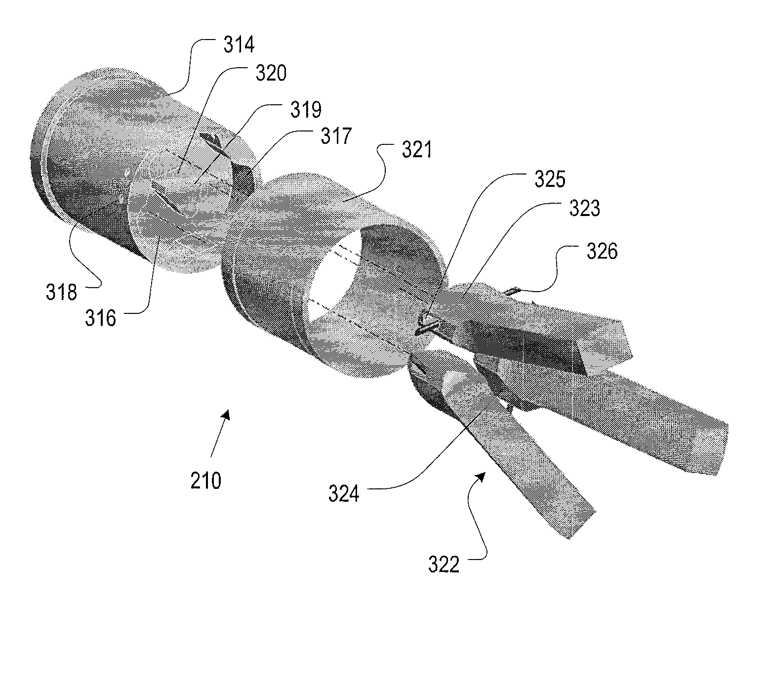
[0041]The terms appearing below are defined for use in this disclosure and the appended claims as follows:[0042]“Operatively Coupled” means that a first object, which might be remote from a second object, can have some effect on the second object or have some effect on a third object through the second object, etc. For example, consider a rigid linkage having a first end and a second end. The first end attaches to a plate and the second end abuts a wall. The linkage is capable of transferring, to the wall, a force that is received at the plate. The linkage and the plate can therefore be considered to be operatively coupled for transmitting a force. Operatively-coupled objects need not be in direct contact with one another and, as appropriate, can be coupled through any medium (e.g., semiconductor, air, vacuum, water, copper, optical fiber, etc.). The coupling between operatively-coupled objects can transmit, as appropriate for the nature of the coupling and the objects, any type of ...


PUM


Abstract

Stacked munitions are launched at high velocity from a launcher by redirecting, to the barrel of launcher, the static load that would otherwise be borne by the nose the projectile in position three for launch. This is accomplished via a load-redirecting pusher plate comprising a load-receiving surface and a plurality of compression members.

Description

STATEMENT REGARDING FEDERALLY-SPONSORED RESEARCH[0001]This invention was made with Government support under N00014-07-C-1103 awarded by the U.S. Navy. The Government has certain rights in the invention.FIELD OF THE INVENTION[0002]The present invention relates to munitions in general, and, more particularly, to weapons capable of launching multiple stacked projectiles underwater.BACKGROUND OF THE INVENTION[0003]FIG. 1 depicts a partial, simplified view of barrel 102 of multi-shoot grenade launcher 100. In launcher 100, three grenades 104-1, 104-2, and 104-3 are “stacked” one behind another in barrel 102. Grenade 104-1 is in position 1 (i.e., first to be launched), grenade 104-2 is in position 2 and grenade 104-3 is in position 3 as the third grenade to be launched. This “stacked” grenade launcher technology is available from Metal Storm Inc. as the “3GL” 3-shot semi automatic modular grenade launcher.[0004]Attached to the aft end of each grenade is propulsion base 108. The propulsion...

Claims


Application Information

Patent Timeline
Patent Type & Authority Applications(United States)
IPC IPC(8): F41F1/00F42B5/02F42B14/06
CPCF41F1/00F42B14/06F42B14/00F42B5/035
Inventor PAULIC, ANTONIO
Owner LOCKHEED MARTIN CORP
Why Eureka
Try Eureka