Over time, a number of serious drawbacks and disadvantages of this design have emerged which imply that this design may not be the best way to meet the challenge of a rapidly accelerating demand for electrical power.
a. While thought to be more efficient than its known alternatives mostly because of its high “tip-speed ratio” (explained below), the ERDA-NASA design may not derive sufficient power from the wind to make it particularly cost-effective in the long run. It has been estimated that generating enough power for a single residential dwelling may require a
propeller at least 25 feet in
diameter. Other estimates suggest that very large
diameter designs, from 125-200 feet, may be needed to achieve outputs in the 100 kilowatts-1000 kilowatts range. As size increases, production, installation, and maintenance costs rise very quickly. Also, given the higher stresses encountered with large, heavy units, failure rates rise making total replacement costs more likely. In addition, the efficient utilization of
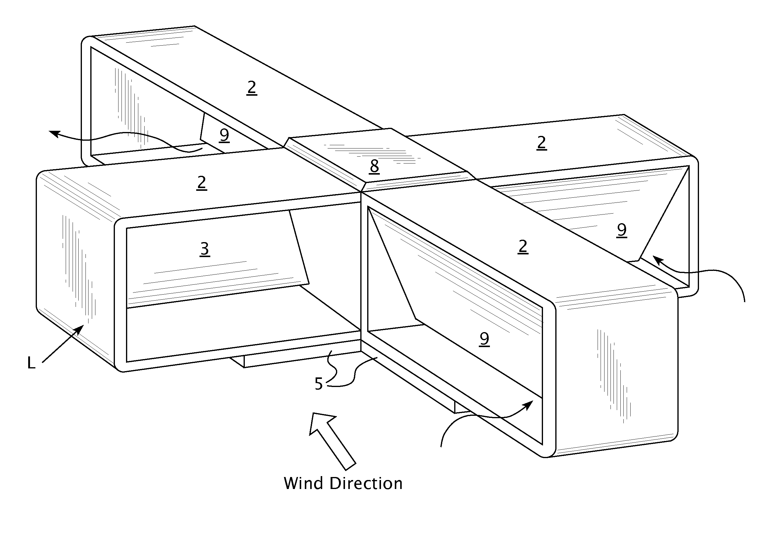
wind power by an ERDA-NASA unit requires supplementary control mechanisms for: turning (or orienting) the unit;
feathering its blades; and overspeed braking in high winds. These control mechanisms use energy to operate—thus decreasing efficiency and further complicating design and production / maintenance costs. Units must be spaced apart roughly 10 times the rotor
diameter to avoid turbulent interference with each other. Consequently, wind farms will occupy considerable acreage for a sizeable number of units. For example, one estimate requires 90 square miles for propellers 125 feet in diameter to produce 100 megawatts. Thus, for any proposed wind farm site, it remains a serious question whether ERDA-NASA units are economically feasible.
b. Safety considerations are also a factor. The higher tip speeds of today's propellers and greater dynamic strains and stresses on the materials used to make same all contribute to
metal fatigue, increasing the risk of catastrophic failures. In addition, there are already abundant concerns about the detrimental effects on
wildlife, especially birds and migratory
fowl and raptors. ERDA-NASA units located near dwellings, or on the tops of tall buildings, also
pose potentially serious hazards to human and
animal life as well as to property. The tops of tall buildings are ideal sites for wind generators since wind speeds are proportionally greater at higher altitudes. In addition, the desire to develop “green” buildings gives ample motivation for incorporating rooftop wind generators into future architectural plans. Unfortunately, ERDA-NASA generators may not be the best answer because of safety issues alone.
c. ERDA-NASA units are not able to utilize
wind power efficiently over a wide range of wind speeds. Current models of the ERDA-NASA wind turbines typically operate at a preferred constant
wind speed of 40 rpm in a range between 6 and 60 mph. The
propeller blades are feathered to prevent damage in high winds (i.e., above 60 mph). Consequently, there are significant energy losses at speeds in excess of 18 mph because the propeller blades
feather to maintain a preferred constant rotation at 40 rpm. There are also significant energy losses at wind speeds less than 18 mph because generator changes (changes in load) must be made to keep that constant 40 rpm rotation. As wind speeds are highly variable, having such a narrow window of optimal wind velocities decreases expected efficiency.
The direction of wind current is itself in constant flux and unpredictable, especially in a small region over periods of great turbulence.
Today's ERDA-NASA devices gradually reposition to take account of directional fluctuations, but by no means exhibit quick responsiveness to such directional changes.
Individual dwellings, recreational vehicles, or marine uses may not readily accommodate smaller scale ERDA-NASA generators in terms of available
physical space, safety and / or aesthetics.
Such an arrangement is hardly “avian friendly,” and indeed might
pose extreme hazards to life and property.
While alternative designs have meant to address some of these shortcomings, it is unlikely that any Darrieus-type design that depends on converting aerodynamic thrust to
rotational energy will significantly improve these efficiency issues.
The size of Darrieus-type turbines that could produce economically feasible capacities of
electricity would have to be quite large posing other challenges to construction, cost-effectiveness and aesthetics.
Due to this common design feature, most Savonius-type devices share a major
disadvantage of
energy loss from “drag.” Drag is the resistance resulting from moving a rigid surface against the wind or fluid medium.
The existence of drag considerably reduces the efficiency of this type of wind generator.
However, these designs do nothing to eliminate or diminish the basic form of drag.
Motion of the convex surfaces of the rigid rotating vanes against even stationary air in a
stator- or housing-protected rotor still produces drag, thus decreasing efficiency.
These latter devices seem to effectively address the problem of drag, but at a cost.
Rotational energy, or some other
energy source, must be spent to operate these opening and closing mechanisms thereby compromising the efficiency of such devices.
It is doubtful that such complex drag-compensating innovations produce an overall increase in efficiency.
In any case, such complex mechanisms add greatly to manufacturing and maintenance costs in any commercial application.
The rotating vanes usually require minimal clearance between the edges of their stationary wind deflecting panels and vanes, creating a drastic sheering effect.
This serious deficit of the Savonius design, together with ther problems with drag, have been used to condemn such devices as impractical for purposes of serious power generation.
This greatly reduces drag resistance even in static air.
The omission of such a comparison is understandable since it is hard to see on what basis the two can be compared.
Of course, such a turbine cannot exist in our world.
In practice,
vertical axis turbines are thought to be very inefficient.
Let us suppose our hypothetical Savonius-type wind turbine makes a poor showing in this regard and is only 20% efficient.
So far, that doesn't sound promising.
At this point, we encounter a serious conceptual problem with the initial attempt at comparison.
Unfortunately, that is a much larger area than the hypothetical 10,000 sq. ft. we're assuming for the comparison basis.
The conclusion we are driven to given initial assumptions is that one cannot possibly construct an ERDA-NASA propeller capable of extracting the same amount of energy as the hypothetical Savonius-type turbine in any given area transverse to the wind.
Furthermore, let's give each such propeller an (unrealistic) efficiency rating of 90%.
What the above comparison illustrates is that the current designs of ERDA-NASA wind turbines, with their relatively narrow, tapered, and often feathered blades, cannot hope to present sufficient energy-capturing surfaces to the wind to compete with Savonius-type turbines.
Unfortunately, the two gravity-flap turbines discussed above, U.S. Pat. No. 5,525,037 and Published Application No. 20040086373, suffer from a feature that makes them seriously less efficient in capturing wind energy.
The main problem with their design is that their gravity-flap vanes are exposed, flat planes.
Of course, as seen above, Savonius-type turbines with
rigid rotor vanes suffer from drag resistance on all but the downwind part of the cycle (and perhaps even there in principle).

