
Absorptive tunable bandstop filter with wide tuning range and electrically tunable all-pass filter useful therein

a tunable bandstop filter and wide tuning range technology, applied in the direction of impedence networks, multiple-port networks, electrical apparatus, etc., can solve the problems of yig based tunable bandstop filters that are bulky, reflected energy could even physically damage the transmitter, and the signal from a nearby wireless transmitter tends to overwhelm an adjacent receiver. , to achieve the effect of wide tuning rang

Active Publication Date: 2012-08-23
HITTITE MICROWAVE LLC
View PDF6 Cites 29 Cited by
  • Summary
  • Abstract
  • Description
  • Claims
  • Application Information

AI Technical Summary

Benefits of technology

[0008]It is therefore an object of this invention to provide an improved, versatile, absorptive tunable bandstop filter with an extremely wide tuning range and to tunable all-pass filter used therein.
[0009]It is a further object of this invention to provide such an improved, versatile, absorptive tunable bandstop filter with an extremely wide tuning range and to tunable all-pass filter used therein in which the stop band frequency can be tuned over more than 3.5:1 tuning ratio.
[0012]It is a further object of this invention to provide such an improved, versatile, absorptive tunable bandstop filter in which the tuning range may be further increased with addition of all-pass filter sections.
[0013]It is a further object of this invention to provide such an improved, versatile, absorptive tunable bandstop filter in which the filter may be implemented on a planar monolithic substrate and the substrate may be mounted on a surface mount package.
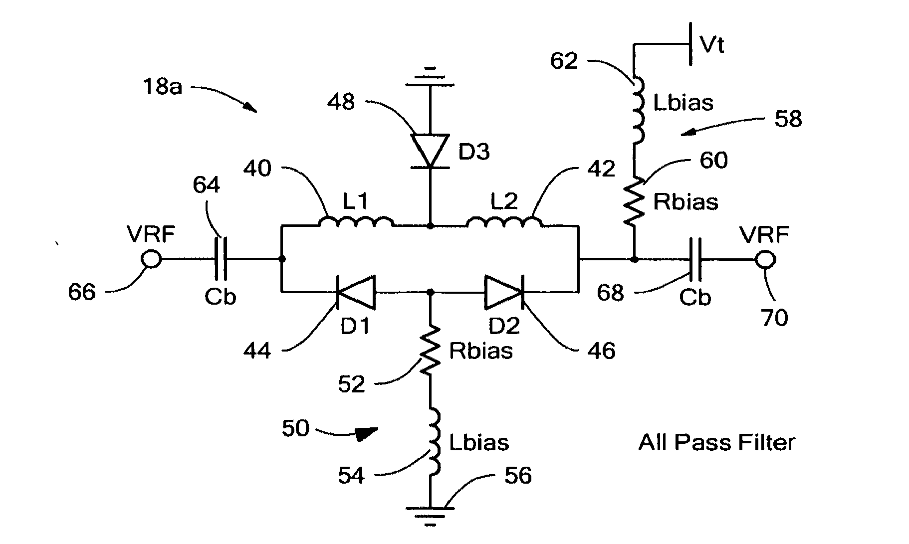
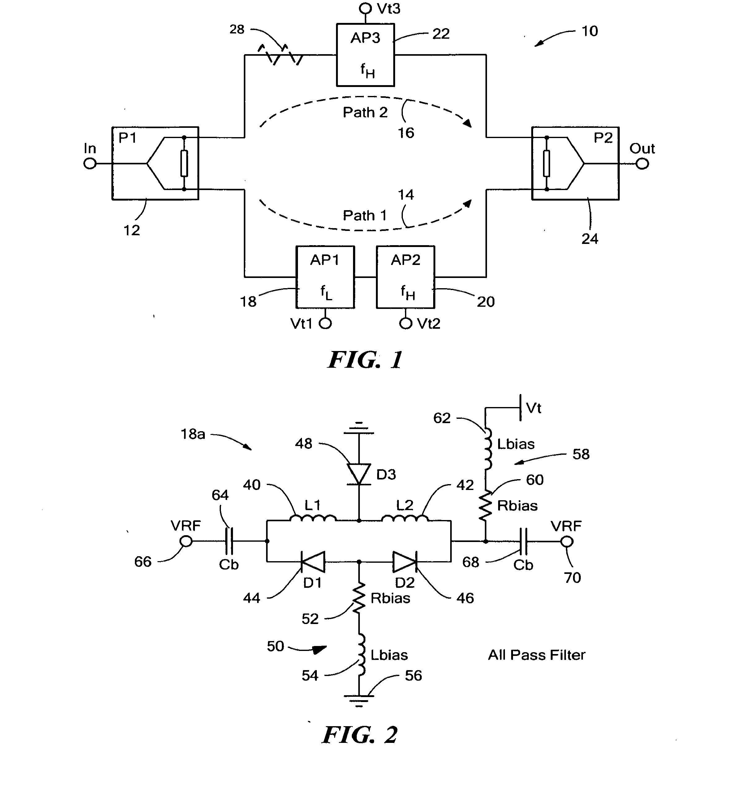
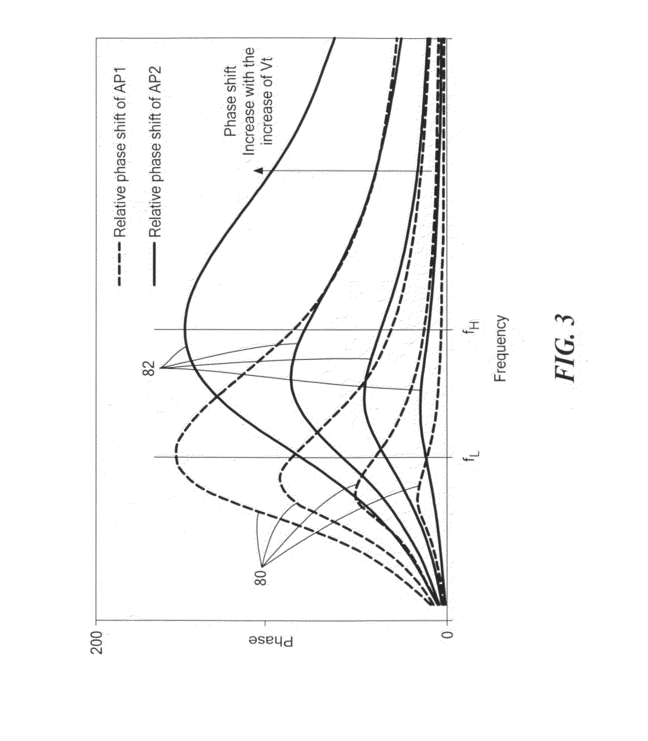
[0014]The invention results from the realization that a truly improved absorptive bandstop filter with wide tuning range can be achieved with a pair of power dividers joined by two branches of all-pass filter networks. Signals are split by the first power divider which also improves the power handling capability. Half the power passes through the upper branch all-pass network(s) and the other half passes through the lower branch all-pass networks. Both signals are recombined at the second power divider. Tuning of the bandstop frequency is achieved by electrically controlling the upper or lower all-pass filter branches, to provide 180° of phase difference with similar amplitude when signals join at the second power divider thereby providing a rejection center frequency tuning ratio of more than 3.5:1, with the flexibility to control the rejection bandwidth as well and having relatively low insertion loss, high power handling, and being readily implementable as a monolithic microwave integrated circuit (MMIC).

Problems solved by technology

With the explosive growth of wireless technology, there are many instances where the signal from a nearby wireless transmitter tends to overwhelm an adjacent receiver.
At high RF power levels, the reflected energy could even physically damage the transmitter.
However, YIG based tunable bandstop filters are bulky and their tuning speed is very slow (compared to electronic tuning).
These drawbacks limit the usage of YIG based bandstop filters in current wireless applications where high integration and high speed are demanding.
There have been many published methods in achieving planar bandstop filters but none have reported the ability to deliver an absorptive bandstop filter that can be electronically tuned over an octave bandwidth or greater, and none have the capability to tune both the rejection frequency and the rejection bandwidth.
This approach, however, uses a phase shifter, and therefore is inherently narrow band.
Also, it does not provide the bandwidth tuning ability.
However, this device requires a large number of resonators to provide a reasonable level of rejection or wider stop band resulting in higher insertion loss over the pass-band.
Also, the rejection bandwidth tuning option is not available.
While it shows low loss and high power handling capacity, the level of isolation between the first and fourth terminals became a limiting factor to the rejection level of the bandstop filter.
Also relying on the quadrature hybrid coupler made it relatively large size and limited bandwidth.

Method used


Image

  • Absorptive tunable bandstop filter with wide tuning range and electrically tunable all-pass filter useful therein
  • Absorptive tunable bandstop filter with wide tuning range and electrically tunable all-pass filter useful therein
  • Absorptive tunable bandstop filter with wide tuning range and electrically tunable all-pass filter useful therein

Examples


Embodiment Construction

[0039]Aside from the preferred embodiment or embodiments disclosed below, this invention is capable of other embodiments and of being practiced or being carried out in various ways. Thus, it is to be understood that the invention is not limited in its application to the details of construction and the arrangements of components set forth in the following description or illustrated in the drawings. If only one embodiment is described herein, the claims hereof are not to be limited to that embodiment. Moreover, the claims hereof are not to be read restrictively unless there is clear and convincing evidence manifesting a certain exclusion, restriction, or disclaimer.

[0040]There is shown in FIG. 1 a preferred embodiment of a tunable bandstop filter 10 in accordance with the present invention. It includes a first input 3 dB power divider P112 and lower path 114 and upper path 216 branches of all-pass filter networks AP118, AP220, AP322 and a second output 3 dB power divider P224. The pre...


PUM


Abstract

This invention features an absorptive tunable bandstop filter with wide tuning range including first and second branches of all-pass filter networks, an input power divider for splitting the input signal and passing approximately half of the input signal power through each said branch of said all-pass filter networks, and an output power divider for recombining the signal power from each said branch of said all-pass filter networks, at least one of said branches of said all-pass filter networks being electrically tunable to provide an approximately 180° phase difference with similar amplitudes of the split said signal power to be recombined at said output power divider for rejecting but substantially absorbing selected frequencies.

Description

FIELD OF THE INVENTION[0001]This invention relates to an absorptive tunable bandstop filter with wide tuning range and to an electrically tunable all-pass filter useful therein.BACKGROUND OF THE INVENTION[0002]With the explosive growth of wireless technology, there are many instances where the signal from a nearby wireless transmitter tends to overwhelm an adjacent receiver. Thus, it is ideal to remove the interfering transmitted frequencies by placing a bandstop, or notch, filter at the output of the transmitter to eliminate harmonic and spurious signals due to nonlinearity of active components such as a power amplifier. Bandstop filters can also be placed at the receiver front-ends to remove interferences due to adjacent receive bands and jammers. It is desirable for a bandstop filter to absorb the rejected signals rather than reflect them back to the previous stage, since at low RF power levels, the reflected signals could interact with the transmitted signals to create interfere...

Claims


Application Information

Patent Timeline
IPC IPC(8): H03H7/00
CPCH03H7/0153H03H7/12H03H2007/013H03H7/20
Inventor ZHANG, CEMINKOECHLIN, MICHAEL
Owner HITTITE MICROWAVE LLC
Learn More