
Method and system for determining navigation parameters of an aircraft

a technology for aircraft navigation and parameters, applied in the direction of speed/acceleration/shock measurement, speed/acceleration/shock measurement, testing/calibration of speed/acceleration/shock measurement devices, etc., can solve problems such as stalling and dropping, aircraft cannot fly safely, aircraft may be damaged

Active Publication Date: 2012-08-23
THALES SA
View PDF2 Cites 20 Cited by
  • Summary
  • Abstract
  • Description
  • Claims
  • Application Information

AI Technical Summary

Benefits of technology

[0015]In this context, the object of the invention is to propose a backup air navigation solution based on the use of radio navigation signals. One advantage of the invention is that it requires the use of only a single antenna unlike the solutions of the prior art.
[0016]The subject of the invention is thus a method for determining navigation parameters of an aircraft, characterized in that it consists at least in determining the geographic speed {right arrow over (V)} of said aircraft, expressed in a given local fixed coordinate system {{right arrow over (i)}, {right arrow over (j)}, {right arrow over (k)}}, obtained from the measurements mi of carrier phase increments Δφi of the radio navigation signals originating from a plurality of the radio navigation satellites in sight of said aircraft and received by a single antenna, each of said measurements m, constituting an estimate of the relative speed of said aircraft relative to said satellite projected onto the sight axis linking the aircraft to the satellite, each of said measurements m, being compensated by the apparent radial speed of the satellite.
[0017]In a particular embodiment of the invention, the geographic speed {right arrow over (V)} is obtained by applying the least squares method to the resolving of the matrix equation m=H{right arrow over (V)}+b, in which m is a vector whose components are said measurements mi of carrier phase increments of each of the radio navigation signals received, b is a vector whose components are the measurement errors, for example due to the thermal noise, affecting said measurements mi, H is the matrix of change of the coordinate system of the satellite sight axes towards said local coordinate system {{right arrow over (i)}, {right arrow over (j)}, {right arrow over (k)}}.
[0018]In a particular embodiment, the method according to the invention also consists in determining the acceleration {right arrow over (γ)} of said aircraft in said local coordinate system {{right arrow over (i)}, {right arrow over (j)}, {right arrow over (k)}}, based on a measurement {right arrow over (γ)}i of the derivative over a given time period of said phase increments Δφi, each of said derivative measurements {right arrow over (γ)}i constituting an estimate of the relative acceleration of said aircraft relative to said satellite projected onto the sight axis between the aircraft and the satellite to which is added the apparent acceleration {right arrow over (γ)}ia of the satellite in the direction of said sight axis to obtain the total acceleration {right arrow over (γ)}ip of the aircraft in the satellite sight axis.
[0019]In a particular embodiment of the invention, the acceleration {right arrow over (γ)} of said aircraft in said local coordinate system is obtained by applying the least squares method to resolving the matrix equation {right arrow over (γ)}p=H{right arrow over (γ)}+b′, in which {right arrow over (γ)}p is a vector whose components are the measurements {right arrow over (γ)}ip of total acceleration of the aircraft on each satellite sight axis, b′ is a vector whose components are the measurement errors affecting said integration measurements {right arrow over (γ)}i, H is the matrix of change of the coordinate system of the satellite sight axes towards said local coordinate system {{right arrow over (i)}, {right arrow over (j)}, {right arrow over (k)}}.
[0020]In a particular embodiment, the method according to the invention also consists in determining the roll angle Φ of the aircraft based on the geographic speed {right arrow over (V)} of the aircraft expressed in the geographic coordinate system {north, east, centre} and the specific force {right arrow over (f)} applied to said aircraft, said force {right arrow over (f)} being deduced from the acceleration {right arrow over (γ)} by subtracting from it the Earth's gravitational field, the roll angle Φ being calculated using the following relationship:Φ=atan(vn·fHe(v→)-ve·fHn(v→)-fHc(v→))in which vn and ve are the normed components of the direction of the geographic speed {right arrow over (V)} on the east and north axes of the local coordinate system {north, east, centre} and {right arrow over (f)}H({right arrow over (v)})={right arrow over (f)}−({right arrow over (f)}·{right arrow over (v)}){right arrow over (v)} is the projection, on the plane orthogonal to the displacement of the aircraft, of the specific force {right arrow over (f)}.

Problems solved by technology

Without these parameters, the aircraft cannot fly safely.
In practice, if this speed is too high, the aircraft may be damaged; if too low, it may stall and drop.
Thus, the measurements performed by the backup pathway are not independent of those delivered by the operational pathway since they are exposed to common failure modes.
This solution presents the drawback of requiring at least two GNSS antennas and increasing the overall dimension in the aircraft.
Furthermore it brings difficulties in synchronizing the two antennas to which are also added problems of resolving ambiguity concerning the carrier phase deviation measured from the two distant antennas.
One general limitation to the use of the satellite radio navigation signals for air navigation lies in the vulnerability of the GNSS receivers with regard to the availability of the signals or the various disturbances linked to the propagation environment, such as the interferences, multiple paths or scrambling problems.
These disturbances are likely to result in significant measurement biases, phase skips and even dropouts of the phase tracking loops thus rendering the service temporarily unavailable.
Although this vulnerability of the GNSS systems has hitherto slowed down their use as primary navigation instrument for an aircraft, they are perfectly compatible with the performance requirements of a backup navigation system having a sufficient availability and accuracy to control the integrity of the measurements supplied by the main system.

Method used


Image

  • Method and system for determining navigation parameters of an aircraft
  • Method and system for determining navigation parameters of an aircraft
  • Method and system for determining navigation parameters of an aircraft

Examples


Embodiment Construction

Checking the Integrity of the Anemometric Systems

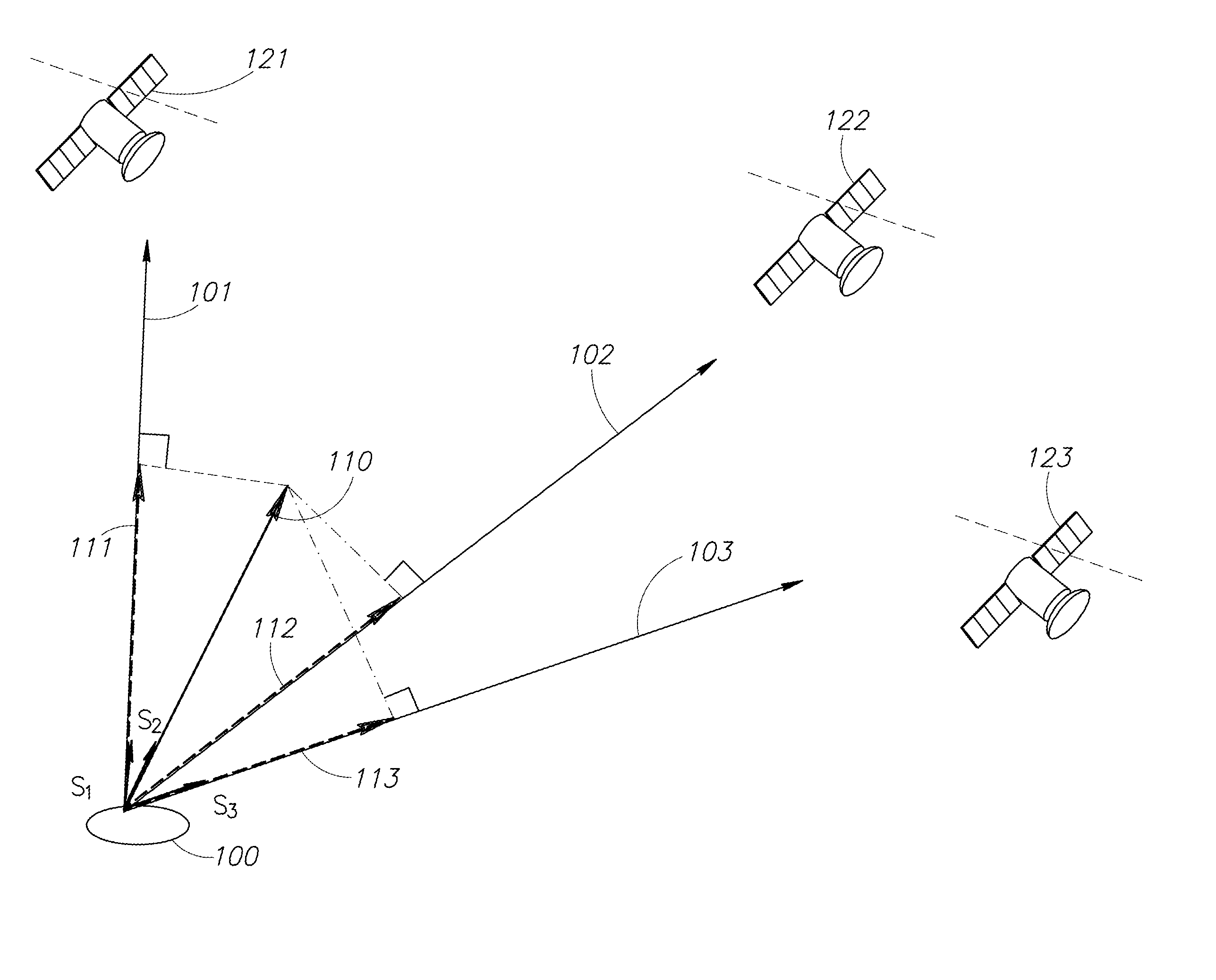
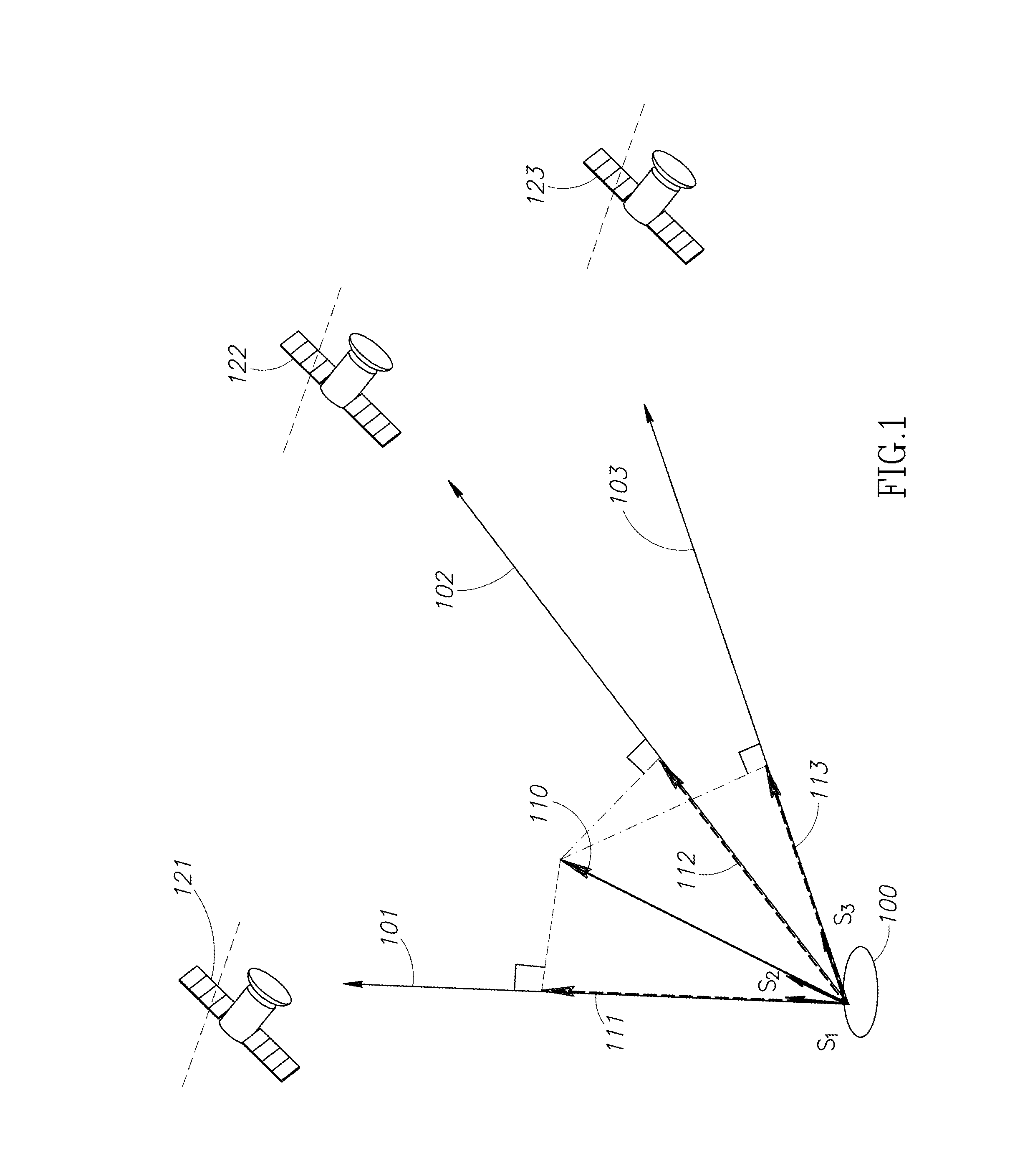
[0030]One of the objectives targeted by the present invention is to propose a check on the integrity of the onboard anemometric systems on the aircraft and / or to complement the backup instrumentation. To this end, the invention makes it possible to determine the real geographic speed {right arrow over (V)} of the aircraft in a local terrestrial coordinate system. The method according to the invention that makes it possible to obtain an estimate of this speed from a single GNSS antenna is developed hereinafter in the description. From the knowledge of the geographic speed {right arrow over (V)}, it is possible to form, by comparison, a check on the speed measurements supplied by the anemometric system or systems. The comparison of the measurement of speed of the aircraft relative to the air (also called air speed), supplied by the anemometric system, with that of the geographic speed, supplied by the invention, implies having an estima...


PUM


Abstract

Method for determining navigation parameters of an aircraft, characterized in that it consists at least in determining the geographic speed {right arrow over (V)}, expressed in a given local fixed coordinate system {{right arrow over (i)}, {right arrow over (j)}, {right arrow over (k)}}, based on the measurements m, of carrier phase increments Δφi of the radio navigation signals originating from a plurality of radio navigation satellites in sight of said aircraft, each of said measurements mi constituting an estimate of the relative speed of said aircraft relative to said satellite projected onto the sight axis linking the aircraft to the satellite, each of said measurements m, being compensated by the apparent radial speed of the satellite.

Description

FIELD OF THE INVENTION[0001]The subject of the present invention is a method and a system for determining navigation parameters, notably the route and the attitude, of an aircraft. The field of the invention is that of air navigation and relates to any type of aircraft, with or without a pilot.[0002]The invention relates in particular to the field of satellite radio navigation.[0003]The invention also relates to the field of securing and monitoring the integrity of the anemometric systems delivering anemobaroclinometric measurements, called primary measurements, enabling the aircraft to be positioned relative to the mass of air.BACKGROUND OF THE INVENTION[0004]The sensors which position an aircraft relative to the mass of air, called anemobaroclinometric sensors, deliver fundamental measurements for the aircraft and its safety. Conventionally, these measurements relate to four physical quantities: total pressure, static pressure, temperature (total or static) and incidence. From the...

Claims


Application Information

Patent Timeline
IPC IPC(8): G01S19/52
CPCG01P1/16G01S19/53G01S19/52G01P21/025
Inventor REVOL, MARCMANDLE, JACQUESBIBAUT, ALAINCOATANTIEC, JACQUES
Owner THALES SA
Learn More