Driving circuit and voltage generating circuit and display unit using the same

a driving circuit and voltage generation technology, applied in the direction of identification means, instruments, computing, etc., can solve the problems of difficult frame symmetry and liquid crystal deformation, and achieve the effect of lowering the drive capability of the common driving circui

Active Publication Date: 2012-08-23
GOLD CHARM LTD
View PDF2 Cites 7 Cited by
  • Summary
  • Abstract
  • Description
  • Claims
  • Application Information

AI Technical Summary

Benefits of technology

[0089]As described above, the present invention allows the effect that it is possible, by placing the common drive circuit at the terminal opposite to the terminal at which the gate driver circuit is placed on the display substrate, to implement the symmetrical frame and narrower frame without lowering the drive capability of the common drive circuit.

Problems solved by technology

If the voltage applied to the liquid crystal layer is constantly unipolar, the liquid crystal display is subject to DC components applied to the liquid crystal layer for a long time, causing problems such as degradation of liquid crystal characteristics.
Although a symmetrical frame design is required for the entire liquid crystal display including the drive circuit, it is not easy to make the frame symmetrical in arranging the common drive circuit IC 40.

Method used


Image

  • Driving circuit and voltage generating circuit and display unit using the same
  • Driving circuit and voltage generating circuit and display unit using the same
  • Driving circuit and voltage generating circuit and display unit using the same

Examples


embodiment

[0047]Next, embodiments of the present invention will be described by referring to the drawings. While the present invention will be described hereafter by using a liquid crystal display, the present invention is also applicable to an active matrix display unit which is more common.

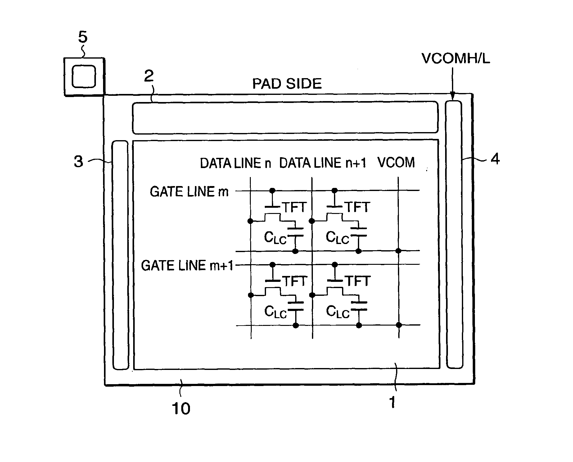
[0048]FIG. 1 is a diagram showing a configuration of a liquid crystal display substrate according to a first embodiment of the present invention. In FIG. 1, a liquid crystal display substrate 10 has a liquid crystal display portion 1 having pixels placed like a matrix, a data driver circuit 2 for driving a data line of the liquid crystal display portion 1, a gate driver circuit 3 for controlling switching of the pixels of each line of the liquid crystal display portion 1, and a common drive circuit 4 for driving a common electrode opposed to a picture electrode of the liquid crystal display portion 1 by sandwiching a liquid crystal layer (simultaneously driving the common electrodes of all the pixels of t...


PUM

PropertyMeasurementUnit
resistanceaaaaaaaaaa
voltageaaaaaaaaaa
resistanceaaaaaaaaaa

Abstract

To provide a liquid crystal display capable of implementing a symmetrical frame and a narrower frame without lowering drive capability of a common drive circuit.
[Solution]
A liquid crystal display substrate 10 has a data driver circuit 2 and a gate driver circuit 3 for driving the liquid crystal display integrated thereon together with a common drive circuit 4, where common voltages VCOMH and VCOML are applied from the outside through a pad. The gate driver circuit 3 is placed to be adjacent to one of the four terminals of the liquid crystal display. The common drive circuit 4 is placed to be adjacent to the terminal opposite to where the gate driver circuit 3 is placed and as close to the pad as possible while having almost the same width as the area of the gate driver circuit 3. The pad close to where the common drive circuit 4 is placed is used as the pad for applying the common voltages VCOMH and VCOML.

Description

CROSS REFERENCE TO RELATED APPLICATIONS[0001]This application is a divisional of U.S. patent application Ser. No. 10 / 664,969, filed Sep. 22, 2003, claiming priority based on Japanese Patent Application No. 2002-278274, filed Sep. 25, 2002, the contents of all of which are incorporated herein by reference in their entirety.DETAILED DESCRIPTION OF THE INVENTION[0002]1. Field of the Invention[0003]The present invention relates to a drive circuit and a voltage generating circuit for a display unit and the display unit using the same, and in particular, to circuits and arrangement thereof in integrating a load drive circuit and the voltage generating circuit on the same substrate as that of a display portion.[0004]2. Prior Art[0005]A liquid crystal display is used in various fields for its advantages such as lightweight, low profile and low power consumption compared to a CRT (Cathode Ray Tube).[0006]Of the liquid crystal displays, as shown in FIG. 9, an active matrix liquid crystal disp...

Claims


Application Information

Patent Timeline
Patent Type & Authority Applications(United States)
IPC IPC(8): G09G5/00G09F9/00G02F1/133G09G3/20G09G3/36
CPCG09G3/3614G09G3/3648G09G2320/0223G09G2300/08G09G2320/02G09G3/3696
Inventor ABE, KATSUMI
Owner GOLD CHARM LTD
Why Eureka
Try Eureka