Real-time and synchronization Internet of things analyzer System Architecture

Inactive Publication Date: 2012-08-23
FUTURE WIRELESS TECH
View PDF12 Cites 145 Cited by
  • Summary
  • Abstract
  • Description
  • Claims
  • Application Information

AI Technical Summary

Benefits of technology

[0056]FIG. 2 is a block diagram of a ISM radio bands high frequency

Problems solved by technology

Second, the low power-usage allows

Method used


Image

  • Real-time and synchronization Internet of things analyzer System Architecture
  • Real-time and synchronization Internet of things analyzer System Architecture
  • Real-time and synchronization Internet of things analyzer System Architecture

Examples


Embodiment Construction

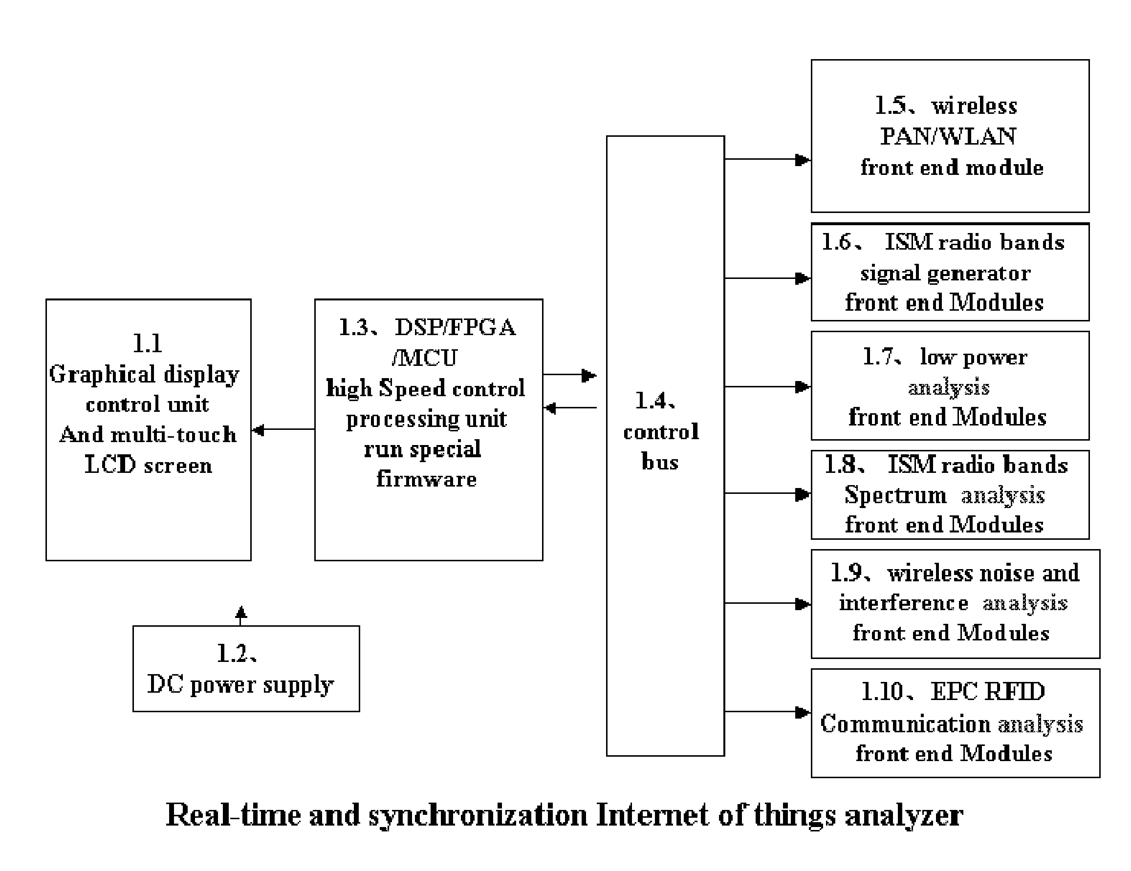
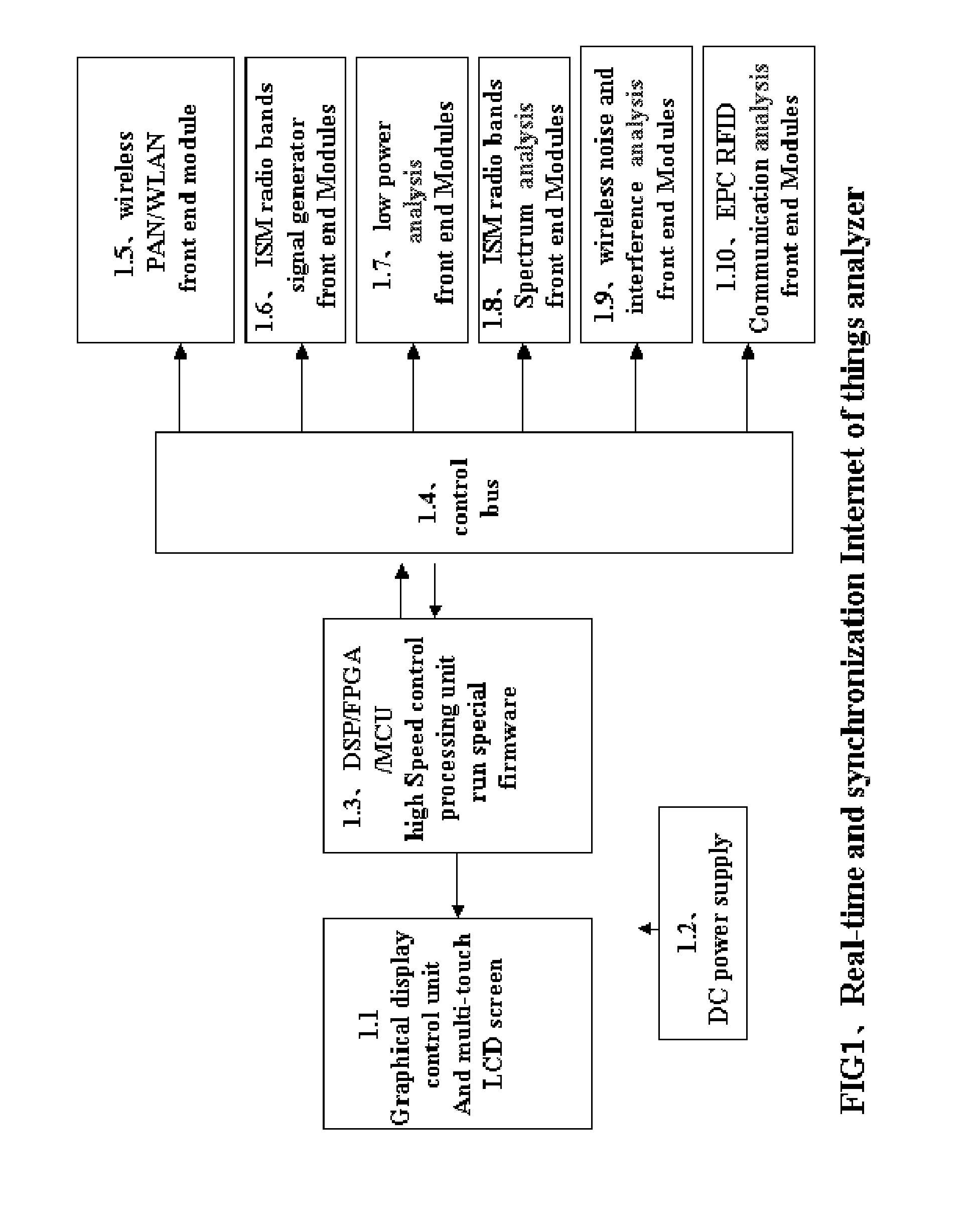
[0062]A Real-time and synchronization Internet of things analyzer System Architecture as FIG. 1;

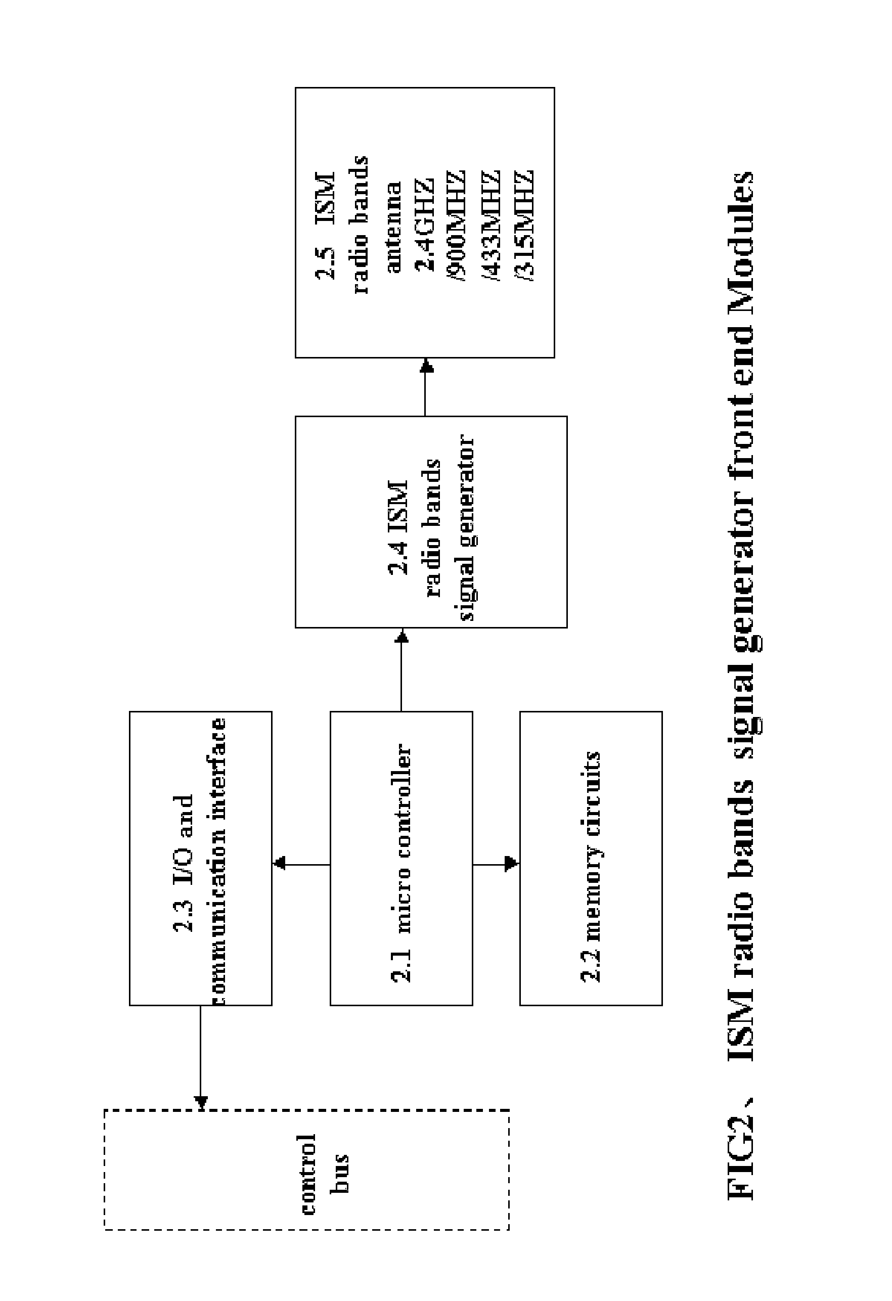
[0063]System are composed of modules which wireless air data collection. Each front end module has a micro control or wireless system on chip (soc) unit; and memory circuits / I / O / communication interface. Using a control bus connects to high speed control processing unit (FIG. 1-1.3). The high speed control processing unit includes digit signal processing unit (DSP) / programming gate array (FPGA) / micro control unit (MCU).

[0064]high Speed control processing unit runs especial firmware to do data encryption, decodes, compression algorithm and more functions, then to send this information to display control unit (FIG. 1-1.1).

[0065]graphical display unit (FIG. 1-1.1), which provide real time analysis and display graphics and curves using multi-touch technology.

[0066]A wireless PAN / WLAN front end modules (FIG. 3) monitor a channel in the air using a high gain antenna (FIG. 3-3.5). Once these pack...


PUM


Abstract

The Internet of things needs using the self-configuring wireless sensors network to interconnect all things.
Using a internet of things analyzer Architecture and methods, we can real time monitor and analysis the wireless network nodes, routing, coordinator to collect the information of the spectrum, the noise, the network of communication protocol, the EPC RFID data communication protocol and the states, low power states . . . .
The architecture and methods will help build the high reliability, long battery life, green Internet of things and wireless sensors network.

Description

BACKGROUND OF THE INVENTION[0001]1. Field of the Invention[0002]The present invention relates to Internet of things and wireless sensor net work.[0003]2. Description of the Related Art[0004]The Internet of things, also known as the Internet of objects, refers to the networked interconnection of everyday objects It is described as a self-configuring wireless network of sensors whose purpose would be to interconnect all things. The concept is attributed to the former Auto-ID Center, founded in 1999, based at the time at the Massachusetts Institute of Technology (MIT);[0005]ZigBee is a low-cost, low-power, wireless mesh networking standard. First, the low cost allows the technology to be widely deployed in wireless control and monitoring applications. Second, the low power-usage allows longer life with smaller batteries. Third, the mesh networking provides high reliability and more extensive range. There are three different types of ZigBee devices: ZigBee coordinator (ZC), ZigBee Route...

Claims


Application Information

Patent Timeline
IPC IPC(8): H04L12/26H04W74/02
CPCH04W24/08Y02D30/70
Inventor SUN, JULAN
Owner FUTURE WIRELESS TECH
Why Eureka
Try Eureka