Low Voltage Differential Signal Driving Circuit and Digital Signal Transmitter

a driving circuit and low voltage technology, applied in logic circuit coupling/interface arrangement, pulse generator, pulse technique, etc., can solve the problems of limited operation voltage, affecting the transmission efficiency of these transmission interfaces, slowing down the signal slew rate etc., to extend the operating frequency range of lvds driving circuits and improve the slew rate

Active Publication Date: 2012-08-30
VIA TECH INC
View PDF21 Cites 5 Cited by
  • Summary
  • Abstract
  • Description
  • Claims
  • Application Information

AI Technical Summary

Benefits of technology

[0006]Low voltage differential signal (LVDS) driving circuits and digital signal transmitters with the LVDS driving circuits are disclosed. The present LVDS driving circuit with a transition accelerator may enhance the slew rate (i.e. accelerate the transition) of the differential output signal and extend the operating frequency range of the LVDS driving circuit.

Problems solved by technology

However, for high speed transmission interfaces, such as a high-definition multimedia interface (HDMI), serial advanced technology attachment interface (SATA interface), peripheral component interconnect express interface (PCIE interface) and so on, the slew rate of the signals of LVDS driving circuits may be slowed down by limited operation voltage, and, transmission efficiency of these transmission interfaces is affected.

Method used


Image

  • Low Voltage Differential Signal Driving Circuit and Digital Signal Transmitter
  • Low Voltage Differential Signal Driving Circuit and Digital Signal Transmitter
  • Low Voltage Differential Signal Driving Circuit and Digital Signal Transmitter

Examples


Embodiment Construction

[0014]The following description shows several exemplary embodiments of the invention, which carry out the invention. This description is made for the purpose of illustrating the general principles of the invention and should not be taken in a limiting sense. The scope of the invention is best determined by reference to the appended claims.

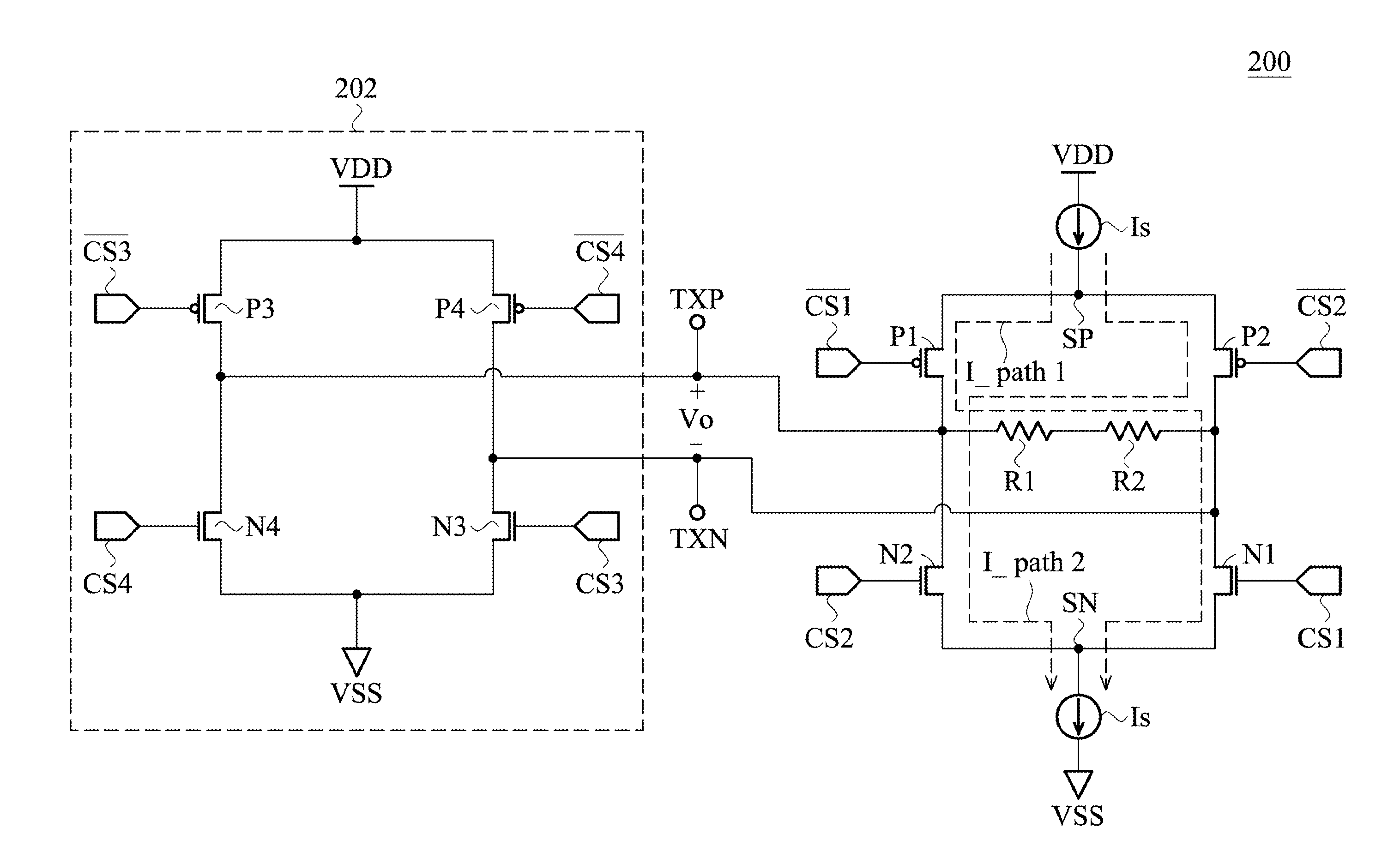
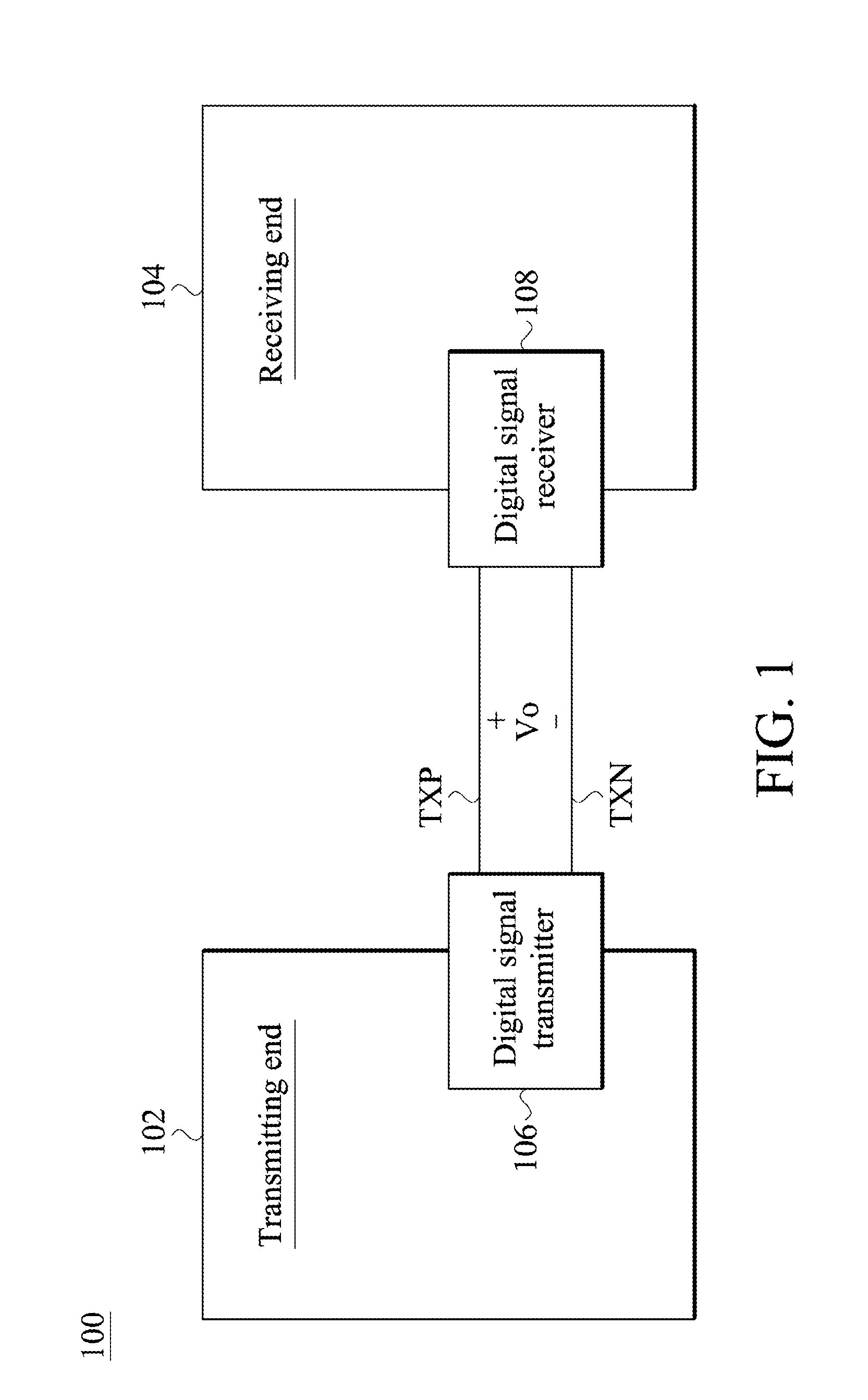
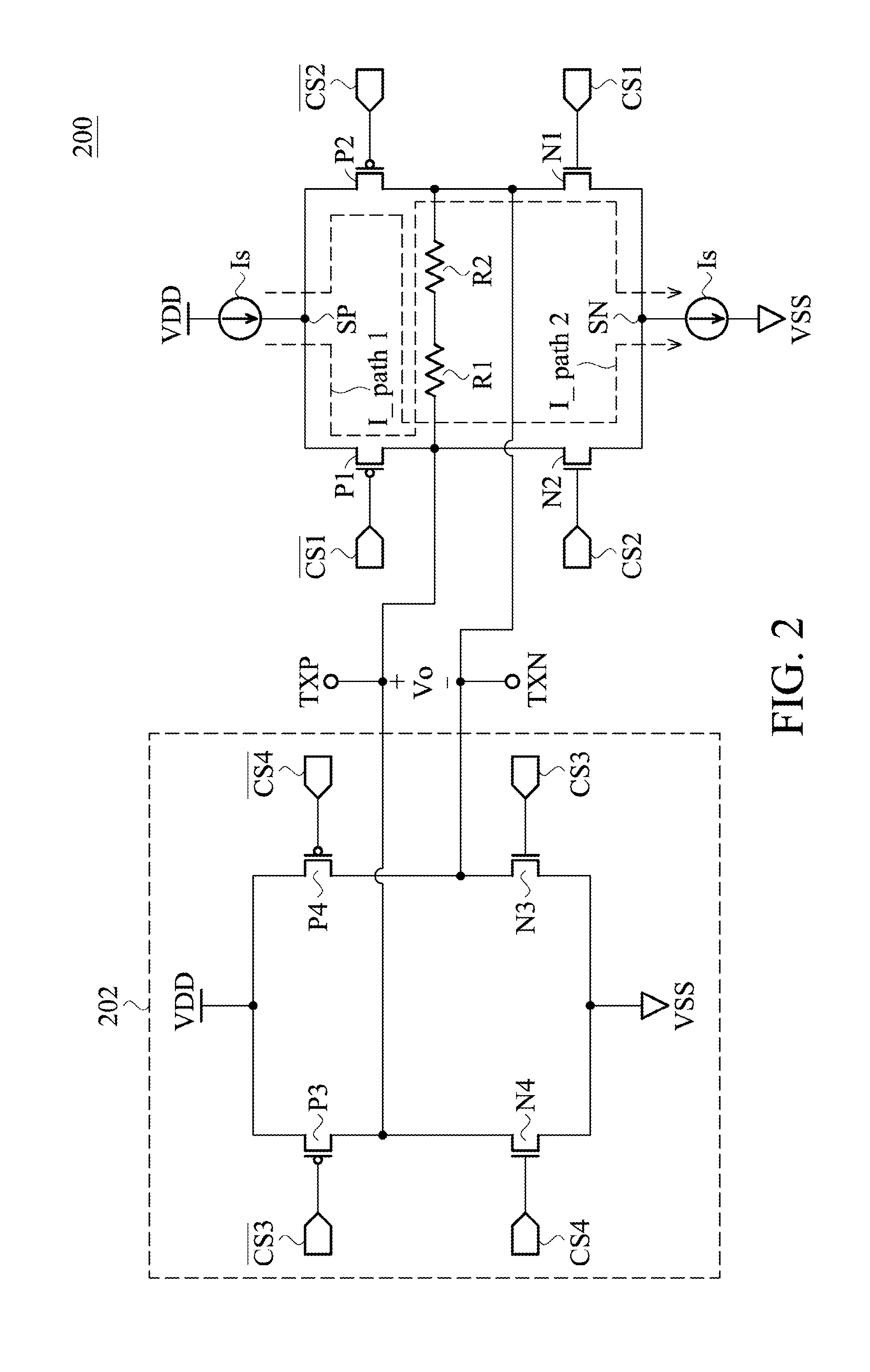
[0015]FIG. 1 illustrates an exemplary embodiment of a signal transceiving structure. The signal transceiving system 100 comprises a transmitting end 102 and a receiving end 104. The transmitting end 102 comprises a digital signal transmitter 106. The receiving end 104 comprises a digital signal receiver 108. The digital signal transmitter 106 utilizes a positive differential output TXP and a negative differential output TXN to provide a differential output signal Vo for digital signal transmission. The digital signal receiver 108 receives the positive differential output TXP and the negative differential output TXN from the digital signal transmitt...


PUM


Abstract

A low voltage differential signal (LVDS) driving circuit and a digital signal transmitter with the LVDS driving circuit are provided. The LVDS driving circuit includes a positive differential output terminal and a negative differential output terminal and a transition accelerator. A differential output signal is provided by the positive and negative differential output terminals. When the differential output signal transits from low to high, the transition accelerator couples the positive differential output terminal to a high voltage source and couples the negative differential output terminal to a low voltage source. When the differential output signal transits from high to low, the transition accelerator couples the positive differential output terminal to the low voltage source and couples the positive output terminal to the high voltage source.

Description

BACKGROUND OF THE INVENTION[0001]1. Field of the Invention[0002]The present invention relates to a low voltage differential signal (LVDS) driving circuit, and in particular relates to improving a slew rate for an LVDS driving circuit.[0003]2. Description of the Related Art[0004]A low operation voltage design is generally used for saving power consumption.[0005]However, for high speed transmission interfaces, such as a high-definition multimedia interface (HDMI), serial advanced technology attachment interface (SATA interface), peripheral component interconnect express interface (PCIE interface) and so on, the slew rate of the signals of LVDS driving circuits may be slowed down by limited operation voltage, and, transmission efficiency of these transmission interfaces is affected.BRIEF SUMMARY OF THE INVENTION[0006]Low voltage differential signal (LVDS) driving circuits and digital signal transmitters with the LVDS driving circuits are disclosed. The present LVDS driving circuit with...

Claims


Application Information

Patent Timeline
Patent Type & Authority Applications(United States)
IPC IPC(8): H03K19/0175H03K3/00
CPCH03K19/018528H04L25/0278H04L25/0272
Inventor LEE, YEONG-SHENGWANG, SCOTT KUENCHIR
Owner VIA TECH INC
Why Eureka
Try Eureka