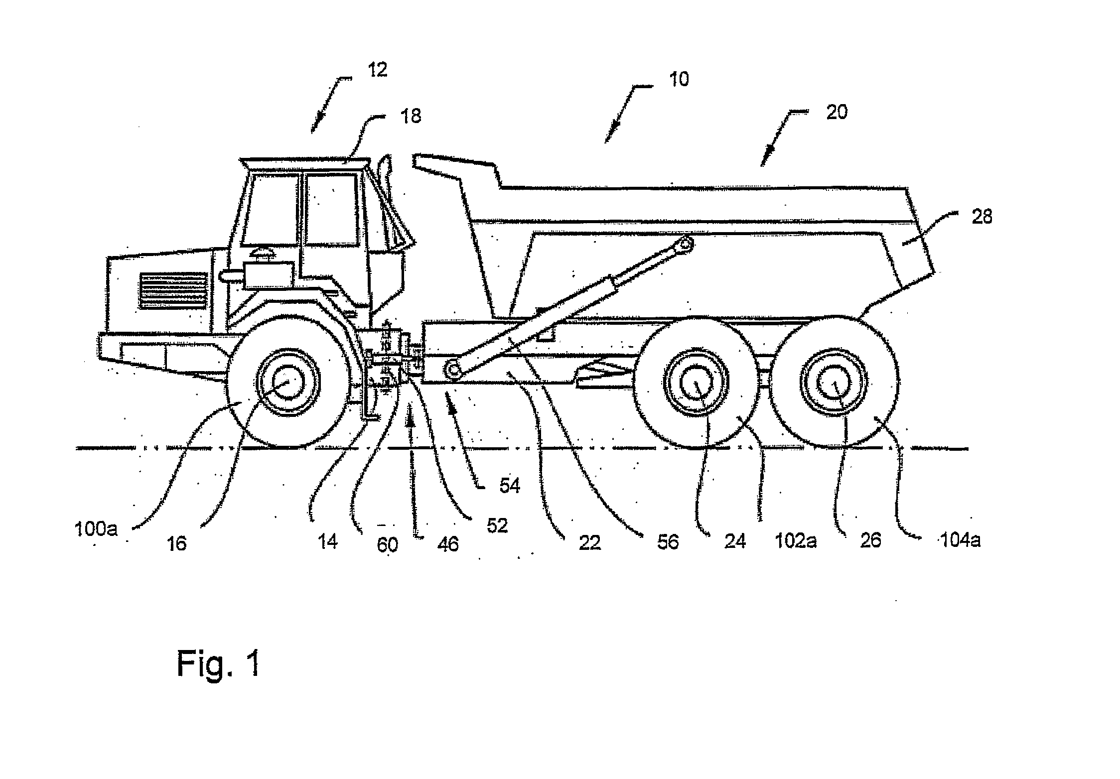
[0034]FIG. 1 depicts a side view of a vehicle 10 in the form of a frame-steered articulated hauler, to which the method according to the invention can be implemented for testing the brake system.
[0035]In the drawings, equal or similar elements are referred to by equal reference numerals. The drawings are merely schematic representations, not intended to portray specific parameters of the invention. Moreover, the drawings are intended to depict only typical embodiments of the invention and therefore should not be considered as limiting the scope of the invention.
[0036]The vehicle 10 embodied as a frame-steered articulated hauler comprises a front vehicle section 12 comprising a front frame 14, a front axle 16 and a cab 18 for a driver. The vehicle 10 also comprises a rear vehicle section 20 comprising a rear frame 22, a front axle 24, a rear axle 26 and a tiltable container 28.
[0037]The front and rear axles 24, 26 of the rear vehicle section 20 are connected to the rear frame 22 via a bogie arrangement (not shown), and will below be referred to as front bogie axle 24 and rear bogie axle 26.
[0038]Each of the front axles 16, the front bogie axle 24 and the rear bogie axle 26 comprises pairwise left and right ground engagement elements, by way of example in the form of wheels. Only the left ground engagement elements 100a, 102a, 104a are depicted. Generally, the term “ground engagement elements” includes wheels, caterpillar tracks etc. By way of example, the ground engagement elements are called wheels and referred to with the same reference numerals in the embodiments.
[0039]The front frame 14 is connected to the rear frame 22 via a first rotary joint 46 which allows the front frame 14 and the rear frame 22 to be rotated relative to one another about a vertical axis 60 for steering (turning) the vehicle 10. A pair of hydraulic cylinders 52 is arranged on respective sides of the rotary joint 46 for steering the vehicle 10. The hydraulic cylinders are controlled by the driver of the vehicle via a steering wheel and/or a joystick (not shown).
[0040]A second rotary joint 54 is adapted in order to allow the front frame 14 and the rear frame 22 to be rotated relative to one another about a longitudinal axis, that is to say an axis which extends in the longitudinal direction of the vehicle 10.
[0041]The container 28 is connected to the rear frame 22 via an articulation (not shown), on a rear portion of the rear frame 22. A pair of tilting cylinders 56 is connected with a first end to the rear frame 22 and connected with a second end to the container 28. The tilting cylinders 56 are positioned one on each side of the central axis of the vehicle 10 embodied as a frame-steered articulated hauler in its longitudinal direction. The container 28 is therefore tilted in relation to the rear frame 22 on activation of the tilting cylinders 56.
[0042]FIG. 2 is a schematic illustration of a system 150 for testing the braking capacity of one or more brake elements of a vehicle according to the invention. This system can be arranged in the vehicle 10 depicted in FIG. 1. The system 150 can be used for accomplishing the method for testing the braking capacity of one or more brake elements 118 according to the invention. As an example a brake element 118 arranged for braking a rotation component in the form of a wheel 100a is schematically illustrated.
[0043]The system 150 comprises a control unit 130 for activating said at least one brake element 118 by applying a predetermined brake force F. The predetermined brake force F is automatically applied after activation of the system, i.e. the operator of the working machine does not need to push a brake pedal to apply the requisite brake force. The system 150 preferably comprises an actuator 138 for activating the system 150. The system further comprises a detection means 34 for determining whether or not there is a motion of the vehicle 10 and/or of said at least one ground engagement element 100a when a decision torque level (yd) is provided by a power source 70, i.e. is applied to the rotation component. The decision torque level (φd) should be indicative for the braking capacity of said at least one brake element 118 when said predetermined brake force F is applied.
[0044]In addition to control the brake force, the control unit 130 is preferably arranged to control the power source 70 for achieving the'requisite torque. The motion of the vehicle 10 is indicated by an arrow 122. The system can also comprise a display unit 136 for displaying a performance status based on results of the test sequences for a brake element 118 tested to an operator. The display unit can be a screen, and/or a loudspeaker system or the like. Also a monitor unit 32 can be arranged for storing performance data of brake tests in order to make these data accessible for maintenance and service.
[0045]Before initiating the test, the power source 70 is preferably in an idling or a stop state and the vehicle 10 is stationary. The brake test starts when the operator activates the system 150 by operating the actuator 138, for example a push button, a lever, a switch or the like. In addition, the gearing of the main transmission 30 of the power source 70 has to be put into an engaged operational state to deliver torque to the wheel 100a.
[0046]The system 150 can activate one or more of the brake elements 118 for braking the vehicle in order to prevent the vehicle from moving. Then the power source 70 is driven to provide the requisite output torque and controlled for example by an accelerator 142 operated by the operator. In another embodiment the power source 70 is automatically controlled to the requisite torque by means of the control unit 130 without any action from the operator such as pushing the accelerator 142.
[0047]In a first alternative, the power source 70 is driven to achieve a decision torque level φd. The torque level is chosen in a way to be indicative of the brake performance when the current brake force F is applied. Alternatively, the system 150 can drive the power source 70 in a first step to achieve an intermediate torque level φi, which is below the decision torque level φd and in a subsequent step to the higher decision torque level φd.
[0048]As soon as the vehicle 10 shows any indication of motion, the test sequence is aborted. The system can also be designed to allow test sequence to be aborted if the operator releases the pressure from the accelerator 142 and/or operates the brake pedal 144 and/or turns off the system 150.
[0049]The flow chart 200 in FIG. 4 depicts a first alternative of the brake test method according to the invention for a vehicle 10 depicted by way of example in FIGS. 1 and 2. When the operator activates the system 150 by operating the actuator 138, the system 150 activates the brake element 118 under test in step 202 by applying a predetermined brake force. The power source 70 is preferably idling or stopped and the vehicle 10 and the ground engagement elements 100a, 102a, 104a are in a stationary state.
[0050]Then in step 204, the power source 70 is driven to achieve a predetermined torque level corresponding to a decision torque level φd applied on the wheel. The decision torque level φd is preferably slightly below the brake moment which can be expected to be provided by the brake element 118 under optimum conditions.
[0051]In step 206 it is determined whether or not a motion of the vehicle 10 and/or of the ground engagement element 100a with the brake element 118 under test occurs when the decision torque level pd is applied to the ground engagement element 100a. If no motion of the vehicle 10 or the ground engagement element 100a is detected (“n” in the flow chart) it is decided that the performance of the brake element 118 under test is good and within the desired limits according to step 210. If the vehicle 10 and/or the ground engagement element 100a has moved (“y” in the flow chart), the brake element 118 has failed the test in step 208 and the test sequence is aborted.
[0052]An alternative of the method according to the invention is depicted in FIGS. 5 and 6. As can be seen in FIG. 5, a torque φ is illustrated as a function of time t. A lower intermediate torque level (intermediate torque φi) can be provided by the power source 70 before a higher decision torque level (decision torque φd) is applied to the wheel. The power source 70 is preferably controlled by the system 150. The intermediate torque φi can be close to the decision torque φd, for example more than 50% of φd or another appropriate percentage of φd, depending on the specific vehicle application requirements.
[0053]As depicted in flowchart 300 in FIG. 6, when the operator activates the system 150 by operating the actuator 138, the system 150 activates the brake element 118 in step 302 with a brake force F. See also FIG. 2. Initially the output torque of the power source 70 corresponds to a torque applied to the wheel 100a which is below a predetermined torque level φi, and the vehicle 10 and the ground engagement element 100a are in a stationary state. Thereafter the torque from the power source is increased.
[0054]In step 304, the power source 70 is driven to achieve a predetermined torque level applied on the wheel 100a, denoted as intermediate torque level φi, which torque level is indicative for the performance of the brake element 118 under test. The intermediate torque level φi is below to the nominal torque level φd which can be provided by the brake element 118 under optimum conditions. The intermediate torque level φi is preferably defined to secure that the vehicle 10 is safe to operate and the brake performance is within a defined margin fulfilling the requirements if the brake element can provide the intermediate torque level.
[0055]In step 306 it is determined if a motion of the vehicle 10 and/or of the ground engagement element 100a occurs when the intermediate torque level φi is applied to the ground engagement element 100a under test. If the vehicle 10 and/or the ground engagement element 100a has moved (“y” in the flow chart), the brake element 118 has failed the test (step 308) and the test is aborted. If the vehicle 10 and/or the ground engagement element 100a has not moved (“n” in the flow chart), it is decided that the performance of the brake element 118 under test is good enough and within the desired limits of the intermediate torque level φi and the test sequence is continued with step 310.
[0056]In step 310 the power source 70 is driven by the system 150 to achieve a higher predetermined decision torque level φd applied on the wheel 100a. This torque level is indicative of the performance of the brake element 118 under optimum conditions.
[0057]In step 312 it is decided if a motion of the vehicle 10 and/or of the ground engagement element 100a has occurred when the decision torque level φd is applied to the ground engagement element 100a with the brake element 118 under test. If the vehicle 10 and/or the ground engagement element 100a has moved (“y” in the flow chart), the brake element 118 has failed according to step 314 and the test is aborted. If the vehicle 10 and/or the ground engagement element 100a has not moved (“n” in the flow chart), it is decided that the performance of the brake element 118 under test is good enough and within the desired limits of the decision torque level φd.
[0058]If the brake test was successful and the brake element 118 has passed the test, the display unit 136 of the system 150 illustrated in FIG. 2 indicates the results to the operator. If the test stage with the intermediate torque level φi was passed but the test stage with the decision torque level φd failed, the system 150 indicates that the vehicle 10 is safe but need brake service after some time, which can be given in more detail depending on e.g. the history of the vehicle 10.
[0059]If both test stages with intermediate and decision torque levels φi and φd were passed, the system 150 can indicate that the brake system has good performance.
[0060]If the test comprised only one test stage with the decision torque level φd, the system 150 can indicate that the brake system is in order or not in order, depending on the test result.
[0061]The brake test method and system 150 can be used to test the complete brake system of the vehicle 10 or to test individual brake elements 118 of ground engagement elements, such as individual wheel brakes. The system 150 can then calculate the total performance of the brake system and/or indicate alternatively an eventual degradation or brake system failure.
[0062]It is to be understood that the present invention is not limited to the embodiments described above and illustrated in the drawings; rather, the skilled person will recognize that many changes and modifications may be made within the scope of the appended claims.